Chapter 5 Installation
28 TI5VG Pentium VP3 ATX Motherboard User’s Manual
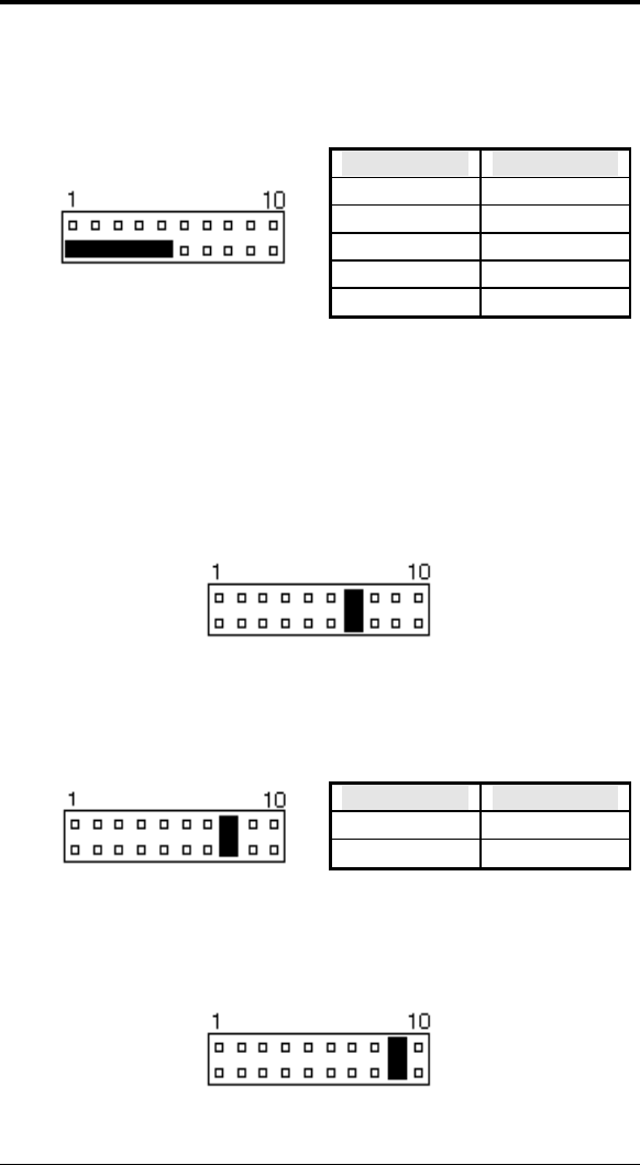
Power LED and Keylock: Pins 11 - 15
The power LED indicates the status of the main power
switch. The keylock switch, when closed, will disable the
keyboard function.
J13 Pin # Signal Name
11 Power LED
12 No connect
13 Ground
14 Keylock
15 Ground
ATX Power ON Switch: Pins 7 and 17
This 2-pin connector is an “ATX Power Supply On/Off
Switch” on the motherboard that connects to the power
switch on the case. When pressed for more than 4 seconds,
the power switch will force the motherboard to power off.
When pressed for less than 4 seconds, it will force the
motherboard to enter the Suspend Mode (depending on
BIOS presettings).
Turbo LED Connector: Pins 8 and 18
There is no turbo/deturbo function on the motherboard. The
Turbo LED on the control panel will always be On when
attached to this connector.
J13 Pin # Signal Name
8 5V
18 Ground
Reset Switch: Pins 9 and 19
The reset switch allows the user to reset the system without
turning the main power switch Off and then On. Orientation
is not required when making a connection to this header.


