64 Publication 1783-UM002C-EN-P - April 2009
Chapter 2
Disconnect Power
After successfully running POST, follow these steps.
1. Turn off power to the switch.
2. Disconnect the cables.
3. Decide where you want to install the switch.
Install and Remove SFP
Modules
These sections describe how to install and remove Small Form-factor
Pluggable (SFP) modules. SFP modules are inserted into SFP module slots on
the front of the switch. These field-replaceable modules provide the uplink
optical interfaces, send (TX) and receive (RX).
Use only Rockwell Automation SFP modules on the switch. Each SFP module
has an internal serial EEPROM that is encoded with security information.
This encoding identifies and validates that the module meets the requirements
for the switch.
You can use any combination of SFP modules. Each SFP module must be of
the same type as the SFP module (or connection type, if an SFP module is not
installed) on the other end of the cable, and the cable must not exceed the
stipulated cable length for reliable communications. See Fiber-Optic SFP
Module Port Cabling Specifications table on page 80 for cable stipulations for
SFP module connections.
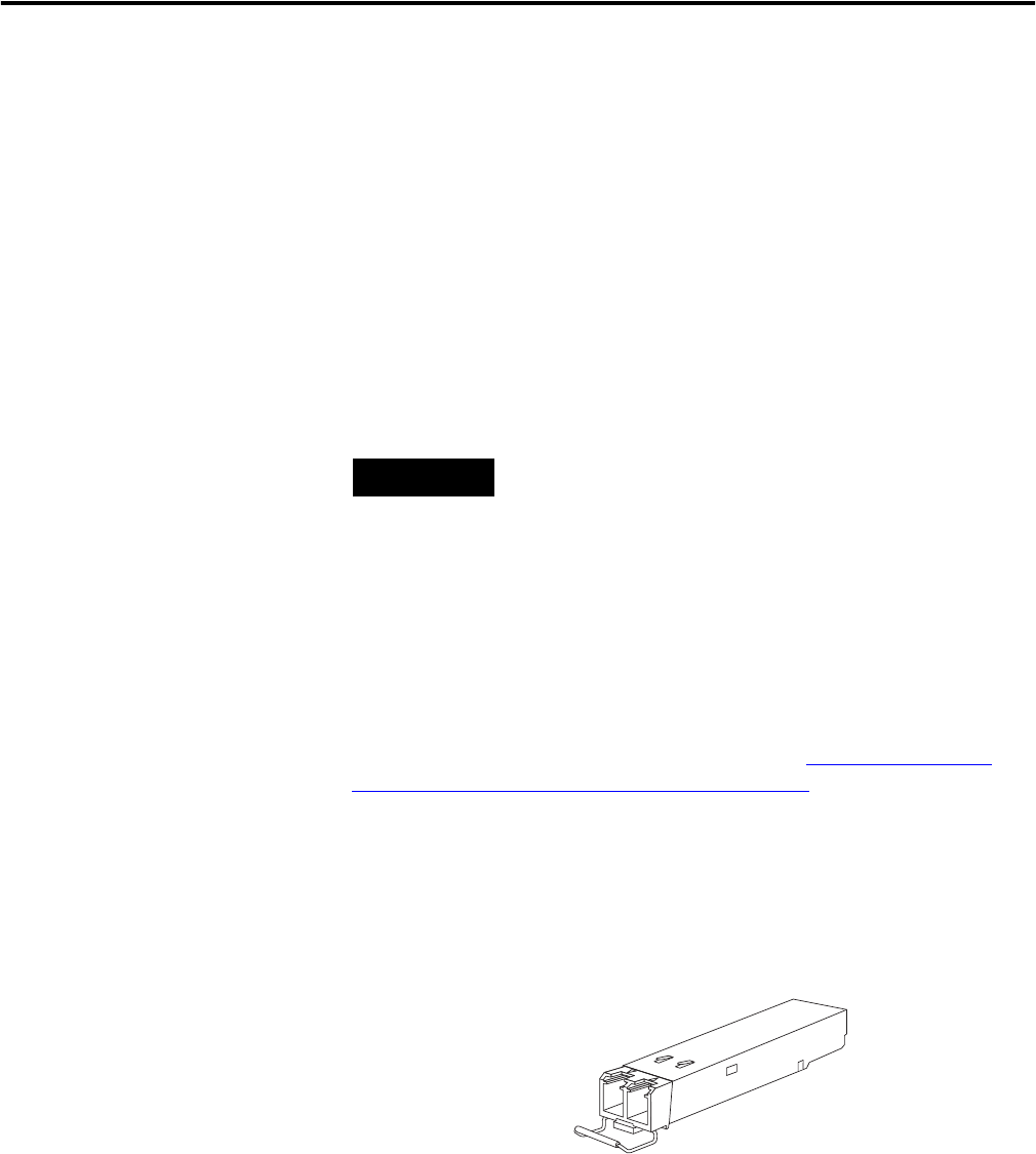
Install SFP Modules into SFP Module Slots
The following figure shows an SFP Module with a bale-clasp latch.
TIP
SFP modules can be installed and removed under power.


