16
C4630 SE HOME AUDIO SYSTEM
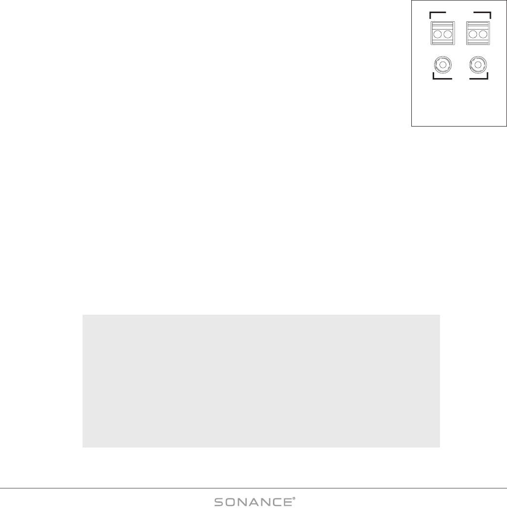
Control Output, Control Input and Sync Connections (see Figure 11)
Control Out Terminal
One 2-wire screw connector that outputs 12VDC @ 100mA when at least one C4630 SE zone is
active. Turns OFF (0VDC) when all zones are OFF. Can be used for triggering external devices
such as a zone-specific external amplifier. Accepts one pair 14 – 24 AWG wire.
CONTROL I
NPUT Terminal
General trigger input that can be used for Paging or sense input as part of a C4630 SE
S
TATUS test in a macro. Requires 5 – 24V AC or DC @ 100mA. Accepts one pair 12 –24AWG
wire.
Wiring the CONTROL Connections
1. Strip approximately ¼" of insulation from each conductor and twist the strands until tight to prevent stray strands.
2. Be sure to maintain proper polarity by connecting the appropriate ‘+V’ and ‘GND’ terminals on the device to the
appropriate ‘+V’ and ‘GND’ terminals on the C4630 SE. Be sure connections are tight and that there are no frayed ends
sticking out that could cause a short-circuit.
SYNC Connections
Two 3.5mm mini jacks used to trigger-link up to four C4630 SEs for Party Mode control (see sidebar) and
provide communication between multiple C4630 SE units that form large systems with more than 6 zones. Use mono
3.5mm mini cables to daisy-chain the Sync jacks of all C4630 SE units in the system.
Audio and IR will pass-through multiple C4630 SEs that are in the Standby mode. Power for the source components should
be managed separately or left ON.
If no other zones are ON and a zone on a C4630 SE is turned ON with a Source button Press, only that C4630 SE and
that zone will turn ON.