MODEL GFC7000EU CO ANALYZER WITH AUTO-REFERENCE
(Addendum to GFC7000E Manual PN 04584)
05134 Rev -
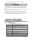
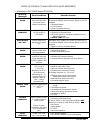
< 0.05 % of reading per °C (5 ppb/°C minimum)
(6)
< 0.05 % of reading per V
7" x 17" x 23.5" (178 mm x 432 mm x 597 mm)
100V 50/60 Hz (3.25A), 115 V 60 Hz (3.0A),
220 – 240 V 50/60 Hz (2.5A)
Installation Category (Over voltage Category) II
Pollution Degree 2
100 mV, 1 V, 5 V, 10 V, 2-20 or 4-20 mA isolated
current loop.
All Ranges with 5% Under/Over Range
1 part in 4096 of selected full-scale voltage
8 Status outputs from opto-isolators
6 Control Inputs, 2 defined, 4 spare
One (1) RS-232; One (1) RS-485/RS-232/Ethernet
Baud Rate : 300 - 115200
CE: EN61010-1:90 + A1:92 + A2:95, EN61326 - Class
A
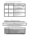
(1)
As defined by the USEPA
(2)
At constant temperature and voltage
(3)
Or 0.2 ppm, whichever is greater
(4)
Or 0.1 ppm, whichever is greater
(5)
Above 10 ppm range, otherwise 0.2 ppm for lower ranges
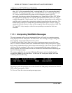
3.1.2. Pneumatic Connections
This section is similar to the one in the manual, with the following exception. The
extra port labeled “From Purge” is the exhaust port for the for the purge gas. The
gas needs to exhausted with a gas line not more than 10 meters long.
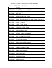
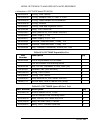
In addition, the GFC7000EU uses a different sample pressure sensor than the
GFC7000E. The GFc7000EU pressure sensor is rated for oxygen service. The part
number is listed in the appendix – spare parts.
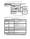
6.13.1.3 Relay alarm outputs