9
TheNetDirectorConsoleKVMSwitchwithIPAccessisdesignedformountingina1Urack
system.Forconvenience,arackmountingkitisincludedwithyourconsoleKVMswitchforquick
installation. The various mounting options are explained in the sections that follow.Standard
Rack Mounting
ThestandardrackmountingbracketsthatcomeattachedtotheconsoleKVMswitchallowthe
unit to be installed in a standard 1U rack by a single individual.
1. Slide out the rear mounting brackets from the console and mount both brackets (separate from
theconsole)totheinsiderearofastandard1Uracksystemusinguser-suppliedscrews.
2.Taketheconsoleandgentlyslideitintothetworear-mountedbracketsintherackandsecure
theconsoleinplacebyinsertinguser-suppliedscrews.
2-Post Rackmounting
TheconsoleKVMswitchcanalsobemountedina2-postrackinstallationusingtheoptional
2-PostRackMountKit(model#:B019-000).Themountinghardwareallowsfortheconsoletobe
openedwiththedrawerinanyposition.Heavy-duty14-gaugesteelprovidesstabilityandprevents
theconsoleframefromtwisting.SeetheB019-000instructionalmanualfordetailedmounting
instructions.
2
3
4
1
5
5.2 Standard Rack Mounting
5.3 Single-Stage Installation
5.4 Two-Stage Installation
5. Installation
(
continued
)
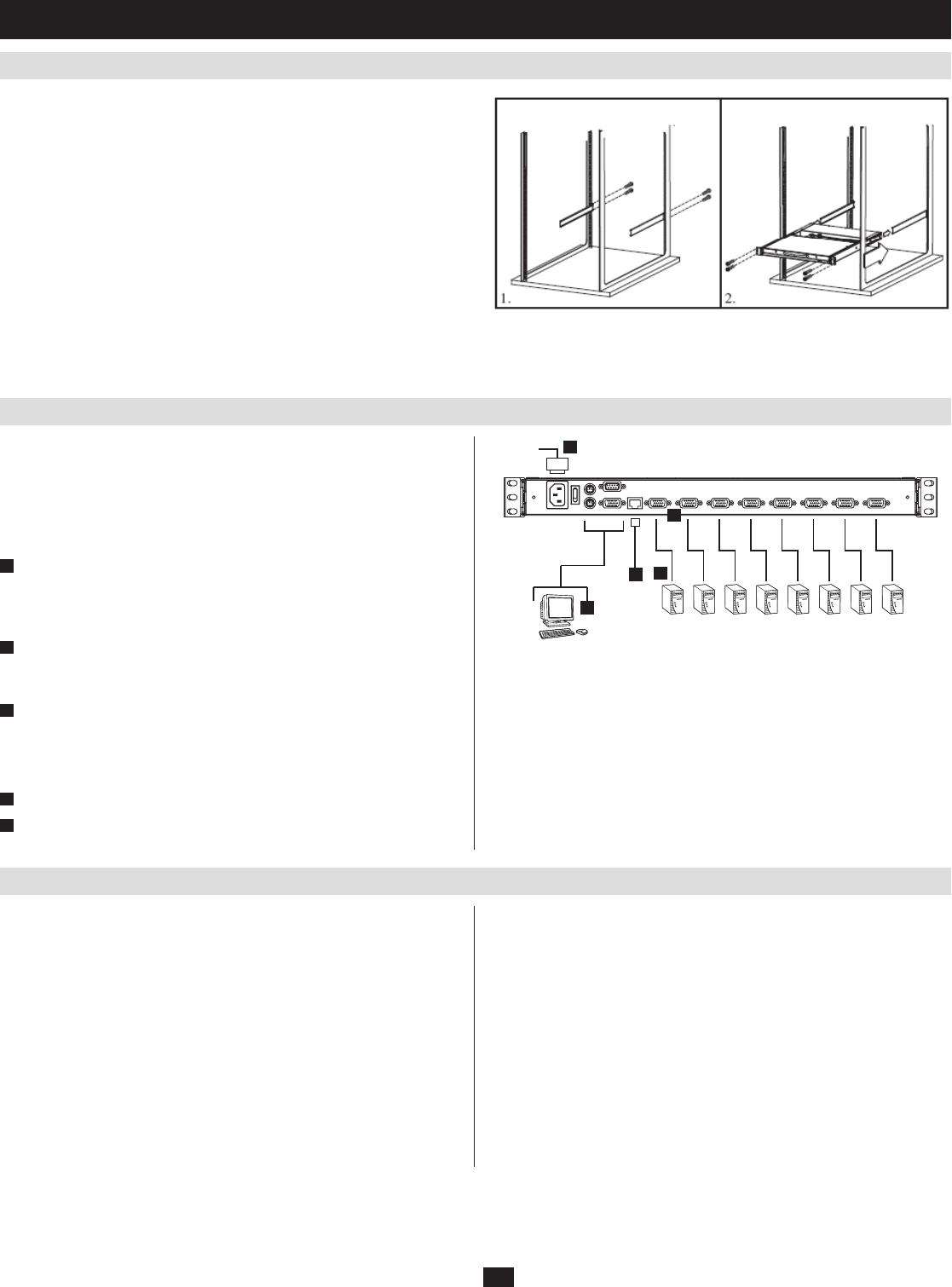
In a Single Stage installation, there are no additional switches cascaded down
from the first unit. To set up a single stage installation, refer to the installation
diagram (the numbers in the diagram correspond to the numbers of the
installation steps) and do the following:
Note: Power off all computers before connecting them to the console KVM
switch.
1
(Optional) If you choose to install an external console, plug your
keyboard, monitor, and mouse into the Console Ports located on the rear
panel. (The external mouse can also be connected to the external mouse
portlocatedontheKeyboardPaneloftheunit.)
2
UsingaP774-Series(PS/2)orP776-Series(USB)KVMcablekit,plug
theyellowcustomHD15connectorintoanyavailableKVMportonthe
switch.
3
At the other end of the cable, plug the keyboard, video (blue), and mouse
connectors into their respective ports on the computer.
Repeatsteps2and3foreachadditionalcomputer/serveryouareconnecting
totheconsoleKVMswitch
4
PlugtheCat5e/6cablefromtheLANintotheLANportontherearpanel.
5
Connect the power cord provided with this package to an AC source and
the power socket.
ToexpandthenumberofcomputersthatcanbecontrolledinyourKVM
installation,upto16*additionalKVMswitches(modelB007-008)canbe
cascadedtoaNetDirectorConsoleKVMSwitchwithIPAccess.Asmanyas
128*computerscanbecontrolledinacompletetwostageinstallation.Ina
twostageinstallation,theNetDirectorConsoleKVMSwitchwithIPAccess
isconsideredtherststageunit;thecascadedB007-008KVMswitchesare
considered second stage units.
*Using a B020-016-17-IP as the first stage unit
To set up a two stage installation, do the following:
Makesurethatpowertoallthedevicesyouwillbeconnectingup,1.
including all preexisting devices on the installation, have been turned off.
UseaP774-Series(PS/2)KVMcablekittoconnectanyavailableKVM2.
Port on the First Stage unit to the Console ports of the Second Stage unit.
After you are all cabled up, you can power on the switch. After the switch is
powered on, power on the computers.
Note: The B020-008-17-IP is pictured above. The only difference between it
and the B020-016-17-IP is the number of KVM ports.
UsetheappropriateKVMcablekits(asdescribedintheCablessectionof3.
theB007-008owner’smanualtoconnectanyavailableKVMportonthe
secondstageKVMswitchtothekeyboard,video,andmouseportsofthe
computers you are installing.
(RepeatSteps2and3foranyadditionalsecondstageKVMswitchesthat
youwishtocascadefromtheNetDirectorConsoleKVMSwitchwithIP
Access.)
Ifitisnotalreadypoweredon,powerontheNetDirectorConsoleKVM4.
Switch with IP Access.
PoweronthesecondstageKVMswitches.5.
Power on the connected computers.6.


