275 Performance
®
2.6
Section 2 • general Boat arrangement
c. Trailer sWiTch
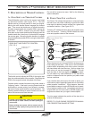
The trailer switch (Power Tilt) is not to be confused
with the Power Trim function. The trailer switch is
to be used only when the engine is off.
The trailer switch allows the drive unit to be raised
for trailering, beaching and launching. To operate,
press and hold the trailer switch until the drive unit
reaches the end of upward travel. The mechanism
that raises the lower unit will stop operating at the
end of the upward travel. To bring the drive unit
down into boating position, push the power trim
switch down.
D. TriM Tabs
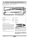
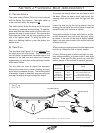
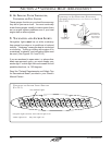
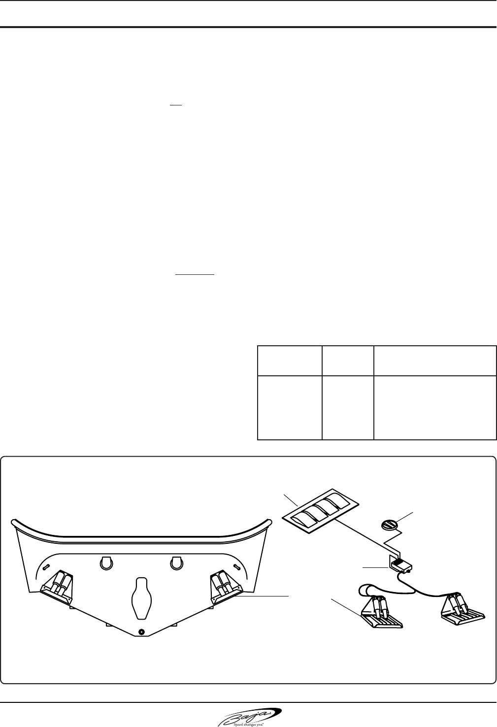
The trim tabs (see Figure 2.6.1) are different from
the stern drive unit trim control. The trim tabs are
two at plates, hinged below the water line on the
transom at the rear and are raised and lowered
hydraulically by using the rocker switches located
at the helm station.
The trim tabs are used to adjust the sideways
listing of the boat due to uneven loading, a strong
cross wind or propeller torque. The twisting effect
of propeller torque is especially pronounced when
running the engine at high horsepower output.
To correct the listing, adjust the trim tabs to level
the boat. When the boat is level, right to left, the
steering effort will be the same for right and left
turns.
Lower the trim tab on the listing (lower) side by
pushing the top half of the rocker switch in one-half
second bursts until the boat is righted.
Using both switches to lower both tabs on a side-
to-side balanced boat will lower the bow, when
on plane, if the rear of the boat is highly loaded.
Again, use only short bursts of the rocker switches
to adjust the trim.
When running at cruising speed, the trim tabs should
be fully up, unless the rear is heavily loaded.
In heavy following seas or when running in an inlet,
best maneuverability is obtained with a bow high
attitude. To be sure the tabs are full up, push the
bottom halves of the rockers for several seconds.
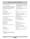
running
attitude
liSt Push
BOW UP
BOW UP
BOW UP
BOW DOWN
BOW DOWN
------
Port
Starboard
Port
Starboard
Top of Both Switches
Top of Starboard Switch
Top of Port Switch
Bottom of Starboard Switch
Bottom of Port Switch
trim taBS
(fig 2.6.1)
The optional installed trim tabs may vary from above picture.
ROCKER SWITCH
CONTROL MODULE
TRIM TAB
TRIM INDICATOR


