


Marine Electrical Prod
ucts
AC & DC Power Distribution Panel
PN 8095 / PN 3095 / PN 8195 / PN 3195
Specications
Material: 0.125" 5052-H32 aluminum alloy
Primary Finish: Chemical treatment per MIL-SPEC C-5541C
Final Panel Finish: Graphite color 2 part textured polyurethane
Maximum Amperage: Varies by components; busbar maximum 100A
Voltage Rating: 8095/3095 12 Volts DC / 120 Volts AC
8195/3195 12 Volts DC / 230 Volts AC
Inches Millimeters
Overall Dimensions: 19-1/2 × 11-1/2 495.30 × 292.20
Features
AC 8095 / 3095 / 8195 / 3195
• 10 AC circuit breaker positions
• 0-50 Ampere AC ammeter with remote sensing coil
DC 8095 / 3095 / 8195 / 3195
• 30 DC circuit breaker positions, twenty-one 15A circuit breakers installed
• 8-16 Volt voltmeter with 3 position switch for multiple battery banks
• 0-100A ammeter with remote shunt
AC 8095 / 3095
• Five 15 Ampere branch circuit breakers installed
• One double-pole 30 Ampere AC main circuit breaker installed
• 0-150 Volt AC voltmeter
AC 8195 / 3195
• Five 8 Ampere branch circuit breakers installed
• One double-pole 16 Ampere AC main circuit breaker installed
• 0-250 Volt AC voltmeter
Guarantee
Any Blue Sea Systems product with which a customer is not satised may
be returned for a refund or replacement at any time.
BlueSeaSystemsInc. Phone(360)738-8230
425SequoiaDrive Fax(360)734-4195
Bellingham,WA98226USA www.bluesea.com
WARNING
] These instructions are intended to provide assistance with the
installation of this product, and are not a substitute for a more
comprehensive understanding of electrical systems. We strongly
recommend that a competent electrical professional perform the
installation of this product.
] If either the panel front or back is to be exposed to water it must be
protected with a waterproof shield.
] The panels must not be installed in explosive environments such as
gasoline engine rooms or battery compartments as the circuit breakers
are not ignition protected.
] The main positive connection must be disconnected at the battery post to
avoid the possibility of a short circuit during the installation of this
distribution panel.
1.DisconnectallACandDCpower
Disconnect all AC power originating on or off the vessel. This includes
inverters, generators, shore power attachments and any other device
capable of supplying AC power to the ship’s circuits.
Disconnect the main positive DC cable from all batteries to eliminate the
possibility of a short circuit and to disable the inverter while installing the
distribution panel.
2.Selectmountinglocationandcutopening
If this panel is to serve as your main shore power disconnect circuit
breaker, select a location which is not more than 10 feet from the shore
power inlet or the electrical attachment point of a permanently installed
shore power cord as measured along the conductors of the feed wires. If
it is more than 10 feet, additional fuses or circuit breakers must be
installed within 10 feet of the shore power inlet.
Select a mounting location which is protected from water on the panel
front and back and is not in an area where ammable vapors from
propane, gasoline or lead acid batteries accumulate. The circuit breakers
used in marine electrical panels are not ignition protected and may ignite
such vapors.
Using the panel template provided, make a cutout in the mounting
surface where the distribution panel is to be mounted. Do not yet fasten
the panel to the mounting surface.
InstallationSetUp DCInstallation
1.Selectpositivefeedwireandnegativereturn
Determine the positive feed (red) and negative return (black or yellow)
wire size by calculating the total amperage of the circuits that will be
routed through the panel. Blue Sea Systems’ electrical panels are rated
at 100 amp total capacity. The positive feed wire must be sized for 3%
voltage drop at the 100 amp panel rating or the maximum amperage
that will be routed through the panel in any particular installation,
whichever is less. It is recommended that the positive feed wire be sized
for the full panel capacity, which, in most cases, will require at least 2
AWG wire, assuming a 10 foot wire run between the panel and the
batteries in 12 volt systems. Refer to the Wire Sizing Chart for other
situations. In the case of panels with two or more columns of breakers,
jumpers from positive bus to positive bus and from negative bus to
negative bus should be the same size as the positive feed and the
negative return wires.
Remember that the length of the circuit is the total of the positive wire
from the power source and the negative wire back to the DC Negative
Bus. Be certain that there is a fuse or circuit breaker of the correct size
protecting the positive feed wire.
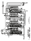
2.Installshunt,positivefeedwireandnegativereturn
The panel is supplied with an external shunt ammeter that must be
connected in the positive feed line to the panel. The shunt may be
mounted at any point in the feed line, but mounting it close to the panel
will keep the sense wires that run to the meter short, minimizing
voltage loss and interference, creating the most accurate meter
reading.
Connect the positive feed wire from the positive source to either of the
2 large bolt terminals on the shunt top. This is now the shunt positive
terminal. Connect two additional lengths of feed wire from the remaining
shunt terminal, now the negative terminal, to both panel positive buses.
Page 1 of 4
8704 Rev. 008