


DCInstallation(continued)
ACInstallation
1.Installbranchcircuitwires
Determine the proper wire size for each branch circuit using the chart
below. Verify that the standard circuit breakers installed in the panel are
correct for each branch circuit. Remove and replace any that are
incorrectly sized. The circuit breaker must have a rating less than the
allowable amperage of the wire, yet greater than the circuit’s
continuous current.
Connect each branch circuit hot (black) to the appropriate load terminal.
Connect each branch circuit neutral (white) to one of the screws on the
neutral bus. Connect each branch safety ground wire (green) to one of
the screws of the safety ground bus.
Do not confuse the neutral current carrying wires (sometimes called
ground) with the green normally non-current carrying wires (sometimes
called grounding). These two wires must be connected only at the source
of power, nowhere else.
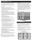
Wiresizingchart
Use the wire sizing chart below to determine the proper branch
and feed circuit wire sizes.
AllowableAmperageofConductors
Next, connect a minimum 16 AWG red wire from the screw on the side of
the shunt positive terminal to the meter positive terminal and connect a
black or yellow wire from the shunt negative terminal to the meter
negative terminal. There should be a 1 ampere fuse in both sense wires
near the shunt terminal. Be certain that on all 4 shunt connections the
wire ring terminals sit directly on the brass blocks of the shunt without any
washers in between.
Connect a negative return wire from both negative buses on the panel
to DC negative.
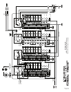
3.Installbatterybankvoltagemonitorwires
The panel is supplied with a meter and switch to monitor the voltage of
three separate sources, usually the batteries. Connect a minimum 16
AWG red wire from each source to be monitored to each of the
corresponding input wires of the switch. There should be a 1 ampere fuse
in each positive wire near each source.
4.Installbranchcircuitwires
Determine the proper wire size for each branch circuit using the
guidelines in step 4. Verify that the standard 15 amp circuit breakers
installed in the panel are large enough for each branch circuit. Remove
and replace with a higher amperage any that are undersized. Connect
the positive (red) branch circuit wires to the load terminals of each circuit
breaker. Connect each negative (black) branch circuit wire to the DC
Negative Bus. DO NOT CONFUSE THE DC NEGATIVE BUS WITH THE
DC GROUNDING BUS.
5.InstallationofBacklightSystem
Connect the yellow negative wire to the panel negative bus.
To activate the label lights by the boat’s battery switch, connect the red
positive wire to the DC panel positive bus.
To activate the label lights by an independent switch or breaker, connect
the red positive wire to the load side of the switch or breaker.
6.Optional—installgroundingsystemwire
The grounding wire (bare, green or green with yellow stripe and normally
non-current carrying) should not be confused with the negative ground
wire (black or yellow and normally current carrying).
In Boatowner’s Illustrated Electrical Handbook, Charlie Wing identies
three purposes of DC Grounding:
1. Holding conductive housings of low voltage (under 50 volts) DC
devices at ground potential by providing a low resistance return
path for currents accidentally contacting the device cases.
2. Providing a low resistance return path for electrical current,
preventing stray currents that may cause corrosion.
3. Grounding metal electrical cases to prevent emission from inside
or absorption from outside of radio frequency noise (RFI).
ABYC requires that grounding wires be sized no smaller than one wire
size under that required for current carrying conductors supplying the
device to which the grounding wire is connected.
7.OptionalBranchLEDs
This panel is supplied with LEDs pre-installed in all optional branch
positions. For future expansion of the panel remove the positive leg of
the LED from the negative bus and connect it to the load side of the
corresponding branch circuit breaker.
8.Optional—Upgradingto24Volts
Remove and replace the existing 8-16V DC voltmeter with an 18-32V DC
voltmeter (PN 8240). Connect the existing meter sense wires to the
new meter, Red Positive wire to “+” and Yellow Negative wire to “-”.
Note
This Blue Sea Systems electrical distribution panel is furnished with 15A
circuit breakers for DC branch circuits. These ratings will satisfy the vast
majority of marine circit protection situations. As shown in the Wire Sizing
Chart, even 16 AWG wire, which is the minimum wire size recommended by
ABYC, has an allowable amperage greater than 20A.
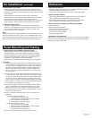
WireSizingChart
1. Calculate the maximum sustained amperage of the circuit. Measure
the length of the circuit from the power source to the load and back.
2. Does the circuit run in an enginespace or nonenginespace.
3. Calculate Famps (Feet x amps). Multiply circuit length by max. current.
4. Base the wire on either the 3% or 10% voltagedrop. In general, items
which affect the safe operation of the boat and its passengers (running
lights, bilge blowers, electronics) use 3%; all other loads use 10%.
5. Starting in the column which has the right voltage and voltagedrop,
run down the list until arriving at a value which is greater than the
calculated Famps. Move left to the Ampacity column to verify that the
total amperage of the circuit does not exceed the maximum allowable
amperage of the wire size for that row. If it does, move down until the
wire ampacity exceeds the circuit amperage. Finally, move left to the
wiresize column to select the wire size.
Example
a. A 12 volt system at 10% drop with a 40’ circuit x 45 amps = 1800
Famps. A wire size of 8 is required.
Note: For wire with 105°C insulation ratingand no more than 2 conductors are
bundled. Not suitable for sizing flexible shore power cords.
8704 Rev. 008
Page 2 of 4