


1.Applybranchcircuitlabelsandmountpanel
Apply a label for each circuit from the label set provided. If the
appropriate label is not included, extended label sets are available
through retail suppliers, and over 500 individual labels are available
directly from Blue Sea Systems. Please go to www.bluesea.com to
order stock or custom labels for specic applications.
Fasten the panel to the mounting surface using the screws provided.
2.Testing
] Reconnect the main positive cable to the battery terminals and turn
the main switch on to supply power to the panel. Turn on all branch
circuits and test the voltage at the panel. Compare this voltage to
the battery terminal voltage to determine that the voltage drop is
within 3%. With all branch circuits still on, test the voltage at one
device on each circuit to determine that there is a 3% or 10% drop
as is appropriate.
]Connect the shore power cable to the boat AC power inlet. Do not
connect the shore power cable to the shore power pedestal. Instead
run the shore power cable such that the shore power plug is next to
the AC panel. With an Ohmmeter verify that the pins of the shore
power plug are connected to the appropriate terminals of the panel.
Refer to ABYC E-11 Figure 13 or 14 or NEC / NEMA documents for
the standard pin arrangements for your plug.
] Connect the vessel’s shore power and verify the Reverse Polarity
light is not illuminated. If the red Reverse Polarity light is on then
either the hot and ground or the hot and neutral wires have been
crossed. Starting at the panel, trace the connections back as far as
necessary to locate the error.
] Using a multimeter where the power source is connected to the
panel verify:
PN 8095 / PN 3095—120 Volt AC
a. 120 volts between hot and neutral
(nominal, this may vary depending on source voltage)
b. 120 volts between hot and ground.
c. 0 volts between neutral and ground.
PN 8195 / PN 3195—230 Volt AC
a. 230 volts between hot and neutral
(nominal, this may vary depending on source voltage)
b. 230 volts between hot and ground.
c. 0 volts between neutral and ground.
] Turn on each branch circuit to verify power to each circuit.
PanelMountingandTesting
Reference
ApplicableStandards
• American Boat and Yacht Council (ABYC) Standards and Recommended
Practices for Small Craft sections: E-1, E-3, E-9.
• United States Coast Guard 33 CFR Sub Part 1, Electrical Systems
UsefulReferenceBooks
• Calder, Nigel (2005). Boatowner’s Mechanical and Electrical Manual
(3d ed). Camden, ME: International Marine / McGraw-Hill.
• Wing, Charlie (2006). Boatowner’s Illustrated Electrical Handbook
(2d ed). Camden, ME: International Marine / McGraw-Hill.
OtherInnovativeProductsfromBlueSeaSystems
• 360 Panel System
• Battery Management Solutions
• AC and DC circuit protection devices
• Waterproof circuit breaker panels
• Fuses, fuse blocks, and BusBar
• Analog and digital meters
QuestionsandComments
We invite your questions and comments. You may contact us at the address
below. To nd out more about our full line of marine electrical products visit
our web site at www.bluesea.com.
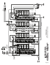
2.Installfeedcircuitwires
Install the feed wires from the shore power inlet or other AC source,
referring to the wire sizing chart to select the correct wire size. Connect
the black AC hot, white AC neutral and green AC safety ground as shown
in the illustration.
If the feed wires are from the shore power inlet or the electrical
attachment point of a permanently installed shore power cord and the
inlet or attachment point is more than 10 feet from this panel,
additional fuses or circuit breakers must be installed within 10 feet of the
shore power inlet. The measurement is made along the conductors.
3.OptionalBranchLEDs
This panel is supplied with LEDs pre-installed in all optional branch
positions. For future expansion of the panel remove the AC hot leg of the
LED from the AC neutral bus and connect it to the load side of the
corresponding branch circuit breaker.
Note
This Blue Sea Systems electrical distribution panel is furnished with 15A or
8A circuit breakers for AC branch circuits. 15A circuit breakers are used in
all 120V panels and 8A circuit breakers are used in all 230V panels. These
ratings will satisfy the vast majority of marine circuit protection situations.
ACInstallation(continued)
8704 Rev. 008
Page 3 of 4