


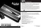
5
Nothing comes close to a Cobra
®
4
English
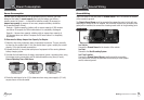
Quick Evaluation Before Installation
•
This section provides you with basic information about the inverter and how
to check its performance before installation.
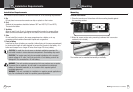
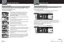
Be Sure to Have on Hand:
A 12 volt DC power source (such as a vehicle battery).
The power source must provide between 11 and 15 volts
DC and be able to supply enough current to run the test
load. As a rough guide, divide the wattage of the test load
by 10 to get the current (in amperes) the power source
must deliver.
A set of cables to connect the power source to the inverter (not included).
The cables must be as short and thick as possible in order to reduce the voltage
drop between the power source and the inverter when drawing current from the
power source.
If the cable suffers an excessive voltage drop, the inverter may shut down when
drawing higher currents because the voltage at the inverter dropped below 10 volts.
#4 AWG stranded copper cable is recommended. It should be no longer than
1.5 meters (4 feet).
The end of the cable that connects to the inverter must have its insulation stripped
off for about
1
⁄2 inch (1.25 cm) back from the end, exposing the bare copper.
The other end of the cable, which connects to the power source, must be
terminated with a lug or other connector that provides a secure, low resistance
connection.
For example, if the power source is a battery, the cable must be terminated
with a battery terminal that clamps to the post on the battery.
A test load that can be plugged into the AC receptacle on the inverter for short
term testing at a low power level. The following cables are recommended for
testing low power level test loads only.
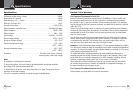
Test Load Power Minimum Cable Size
100w #16 AWG copper
250w #12 AWG copper
500w #8 AWG copper
Quick Evaluation Before Installation
Introduction
Quick Evaluation Before Installation
Introduction
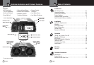
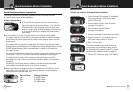
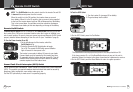
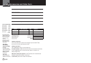
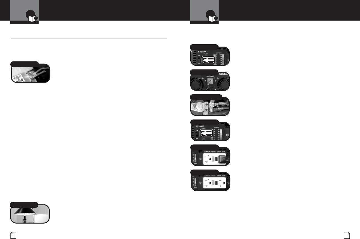
To Check Your Inverter’s Performance Before Installation:
1. Turn the inverter Off (see page 15 for details).
If the power source is a DC power supply,
switch it Off as well.
2. Connect cables to Power Input Terminals
(see page 8 for details).
3. Connect cables to Power Source
(see page 8 for details).
4. Check to make sure all connections are secure.
5. Turn the inverter On. If the power source is
a DC power supply, switch it On first.
6. Plug in the test load.
The inverter should supply power to the load.
If the inverter is not working properly, refer to
the Troubleshooting Guide on page 21 or Power
and Protection Indicators section on page 18.
7. Test the GFCI Outlet (see page 16 for details).
Test Load
On/Off Switch to Off
Connect Terminals
Connect Power Source
On/Off Switch to On
Connect Test Load
Test GFCI Outlet
Power Supply