


11
4 Construction
The pump’s housing is made of a special high
impact plastic designed to reduce interference
from electromagnetic fields and to dissipate
electrostatic discharge. It is composed of two
sections: the base and cover housing. The
pump housing is sealed to ensure that the
pump is water resistant. The battery compart-
ment is not water resistant.
NOTE:
The CADD-Prizm
®
ambulatory infusion
pump is water resistant, but not waterproof.
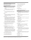
The battery compartment is accessed through a
removable door on the side of the base hous-
ing. Within the battery compartment is space
for the battery and the two battery contacts.
The Medication Cassette reservoir or the
administration set is attached to the bottom of
the pump by inserting the two hooks on the
cassette into the mating hinge pins on the pump.
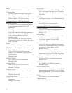
The pump and the reservoir or the administra-
tion set are then placed in an upright position
on a firm, flat surface. The reservoir or the
administration set can be latched in place by
inserting a coin in the slot on the pump’s
latching button, pushing the button in, and
turning the button one-quarter turn counter-
clockwise. The reservoir or the administration
set is locked into place by inserting a key into
the pump’s lock and turning the lock one-
quarter turn counterclockwise.
NOTE:
The cassette lock must be unlocked before
attempting to unlatch the disposable.
NOTE:
The Medication Cassette reservoir and the
administration set are intended for single
use only.
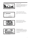
The keyboard, located on the front housing, is
composed of nine membrane switches and is
sealed against moisture. All of the keys contain
domes to provide a tactile feel when the key is
pressed. The keyboard keys are sensed by the
pump’s microprocessor.
The custom Liquid Crystal Display (LCD), also
located on the front housing, shows the pump
status and programmed settings. The dot
matrix display consists of 21 character col-
umns with 4 rows of characters, and is selected
by the pump’s microprocessor according to
status conditions and keyboard entries.
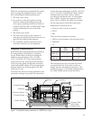
The microprocessor and other circuitry which
control the pump are located on two printed
circuit boards. The microprocessor board
contains the Central Processing Unit (CPU)
and its associated circuitry, motor driver
circuitry, and other miscellaneous circuitry.
The LCD board contains the Liquid Crystal
Display with its associated circuitry, and the
backlight module with its associated circuitry.
The pumping mechanism subassembly contains
the motor, gear train, camshaft, valves,
expulsor, sensing disk, infrared light source,
infrared detector, occlusion sensor, cassette
sensors, lock and latch. Via the motor driver
circuitry, the pump’s microprocessor controls
motor rotation.
Two external port connectors are utilized for
communication and external power input. One
of these connectors, the data in/out jack, is
used for attachment of the Remote Dose cord.
This enables the patient to use either of two
options to begin a Demand Dose when using
the PCA delivery mode: (1) the Remote Dose
button; or (2) the DOSE key.
This jack can also be connected to an external
printer via the interface cable. With this feature,
the patient or clinician can print various pump
reports. The second port is for external power
connection. This port, the power jack, can
receive input from either an AC adapter or the
External Power Source rechargeable power pack.
Connections between the printed circuit boards
are designed for ease of manufacturing and
serviceability. The keyboard is connected to the
microprocessor board via a flex circuit tail.
Flexible circuitry and discrete wires connect
the pumping mechanism, motor, and sensors to
the printed circuit boards.