


3
20°
20°
20°
20°
20°
20°
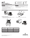
11. Adjust the tension screw until the proper belt tension is
recorded by the Browning Belt Tension Checker. The
recommended deection force is 150 percent of the Edge
value or the value given for a new belt in form 5453 included
with the Browning Belt Tension Checker
WARNING! The surface on which the Motor Base is mounted must be at. A base that is distorted or warped will not function
properly. If the surface is not at, correct the condition with shims.
Maintenance
Lubrication
The carriage tubes are provided with holes or tting for lubrication. Every six months or as dictated by the application, wipe down the
carriage rails and tension rod with an oily rag and apply a light grade grease. Be sure to remove all foreign material from the tubes
and tension rod.
Changing Belts
Turn the tension rod counter clockwise to move the carriage enough to allow the old belt to be removed.
Repeat steps 7 through 11 of the installation instructions to install the new belt.
Adjusting Belts
Periodic adjustment should not be needed. However, if it is suspected that the belt tension is not correct, then complete steps 10 and
11 of the installation instructions.
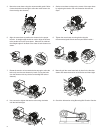
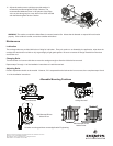
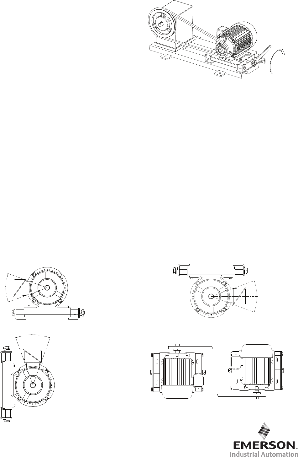
Allowable Mounting Positions
Floor Mounted Ceiling Mounted
Wall Mounted Driven
beside Driver
Browning, Emerson and Emerson Industrial Automation are trademarks of Emerson
Electric Co. or one of its affiliated companies.
©2014 Emerson Power Transmission Corp., All Rights Reserved.
MCIM14006E • Form 9884E • Printed in USA
Wall Mounted Driven
Above Driver
All other mounting positions contact Application Engineering.