


Temperature Calibrator
Using Source Mode
27
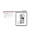
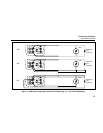
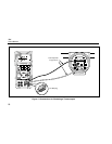
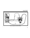
Simulating Thermocouples
Connect the calibrator TC input/output to the instrument
under test with thermocouple wire and the appropriate
thermocouple mini-connector (polarized thermocouple
plug with flat, in-line blades spaced 7.9 mm [0.312 in]
center to center).
Note
One pin is wider than the other. Do not try to
force a miniplug in the wrong polarization. Figure
13 shows this connection.
Proceed as follows to simulate a thermocouple:
1. Attach the thermocouple leads to the appropriate TC
miniplug, then to the TC input/output as shown in
Figure 13.
2. If necessary, press
M for SOURCE mode.
3. Press
T for the TC display. If desired, continue
pressing this key to select the desired thermocouple
type.
4. Enter the temperature you want by pressing
X and
W keys. Press Y and Z to select a different digit to
edit.
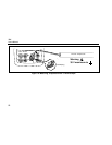
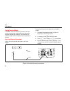
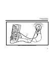
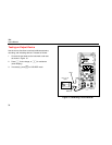
Simulating RTDs
Connect the calibrator to the instrument under test as
shown in Figure 14. Proceed as follows to simulate an
RTD:
1. If necessary, press
M for SOURCE mode.
2. Press
R for the RTD display.
Note
Use the 3W and 4W terminals for measurement
only, not for simulation. The calibrator simulates
a 2-wire RTD at its front panel. To connect to a
3-wire or 4-wire transmitter, use the stacking
cables to provide the extra wires. See Figure 14.
3. Enter the temperature you want by pressing
X and
W keys. Press Y and Z to select a different digit to
edit.
4. If the 724 display indicates ExI HI the excitation
current from your device under test exceeds the limits
of the 724.