Installation Guidelines
A typical installation and connection routine for the searchlight with a Variable Speed Gearbox is as
follows:
Referring to wiring diagram C22801, a supply is fed to the Control Panel, which then provides a
common feed to the Motor Gearbox, Power Supply Unit and the Searchlight Control Panel.
The searchlight has been pre-wired with 3 meters of cable from the gearbox to junction box
provided.
Cables required to be connected by the customer: -
4 core 6mm cable from the Junction Box to the PSU, doubling up the pairs,
3 core 2.5mm cable from the Junction Box to the Control Panel.
4 core 1.5mm cable from the Junction Box to the Control Panel.
12 core 0.5mm cable from the Junction Box to the Control Panel.
Optional Slave Panel Wiring
8 core 0.5mm
2
cable from the Slave Panel to the Junction Box.
The Mains cable to the Control Panel and 3 core 2.5mm cable from the PSU to the Control Panel
(terminals 6 & 7) both to be supplied by the customer.
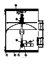
The searchlight head is pre-wired along with the connecting cable to the motor gearbox.
Basic Operation
When the searchlight is switched on a supply is fed to the PSU and linked to the ignitor. Also from
the PSU, a dc output is fed to the lamp.
The ignitor ionises the gas within the lamp and this strikes the light.
All other facilities are fed via the control panels and motor gearbox.


