


9
3. ADJUSTMENTS
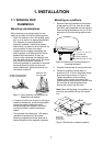
3.1 Installation Check
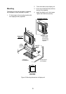
After installing the system it is a good idea to
check it for proper installation, following the
checklist provided below.
•
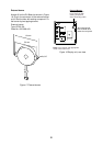
Cable gland is facing toward the stern.
•
Four fixing bolts securing the antenna unit
are securely tightened.
•
The antenna cable is waterproofed at the
base of the antenna unit.
•
The antenna cable is securely retained
against the mast or mounting and is free of
interference from running rigging.
•
The cable gland on the deck or bulkhead is
waterproofed, if provided.
•
Connectors of external equipment are
securely plugged into the radar display unit.
•
The power connections to the battery are of
correct polarity.
3.2 Exchanging Display
Unit of Previous
Model
When exchanging the display unit of the
MODEL 1621/1621 MARK-2 with that of the
MODEL 1622, it is necessary to maintain the
magnetron warmup time. This should be done
with the radar in stand-by.
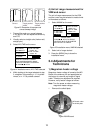
1. Press ▲ and ▼ together for about 10
seconds to show the display shown in
Figure 19.
NAV DATA (NMEA 0183)
GLL BWR BWC GLC GTD
RMA RMG RMC VTG MTW
DBT DBS DPT GGA
PROGRAM NO
03591610XX
SEL MENU
BY KEY
MAIN
DEMO
▲
▲
/
MODEL M1622 M1621/M2
DISPLAY
1
2
Figure 19 Maintenance menu
2. Select MODEL by
▲
.
M1622: 1 minute.
M1621/M2: 1minute and 30 seconds.
3. Select M1621/M2 by
4
.
4. Press the [MENU] key to close the menu.
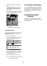
3.3 Adjustments
Do the following in order to adjust the radar.
1) Adjustment of picture
1. Press the [POWER] key on the display unit.
The display should light. In approximately
one minute, ST-BY appears at the screen
center.
2. When ST-BY appears press the [TX] key.
The radar will start transmitting, and you
will probably see some targets, even
though the radar is not yet properly
adjusted.
3. Adjust the sensitivity to display a small
amount of noise on the screen.
4. Press the [–] key several times to select
the minimum range. Adjust the STC to
display nearby radar targets clearly on the
screen. Too much STC action will eliminate
small targets, and too little STC action will
cause the screen to be so full of targets
and noise that it is hard to determine which
target is which as compared to visual
sightings.
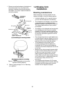
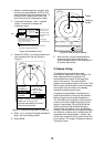
2) Heading alignment
You have mounted the antenna unit facing
straight ahead in the direction of the bow.
Therefore, a small but conspicuous target dead
ahead visually should appear on the heading
mark (zero degrees).
In practice, you will probably observe some
small error on the display because of the
difficulty in achieving accurate initial positioning
of the antenna unit. The following adjustment
will compensate for this error, up to ±30
degrees.