


1
1. INSTALLATION
1.1 Antenna Unit
Installation
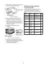
Mounting considerations
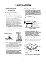
When selecting a mounting location for the
antenna unit keep in mind the following points.
• Install the antenna unit on the hardtop, radar
arch or on a mast on an appropriate platform.
(For sailboats, a mounting bracket is
optionally available.) It should be placed
where there is a good all-round view with, as
far as possible, no part of the ship’s
superstructure or rigging intercepting the
scanning beam. Any obstruction will cause
shadow and blind sectors. A mast, for
instance, with a diameter considerably less
than the width of the antenna unit, will cause
only a small blind sector. However, a
horizontal spreader or crosstrees in the same
horizontal plane would be a much more
serious obstruction; place the antenna unit
well above or below it.
Antenna unit mounted
on top of wheelhouse
Antenna unit
fixed to mast
Figure 1 Typical ant
e
nna unit placement on
powerboat and sailboat
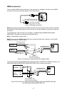
• In order to minimize the chance of picking up
electrical interference, avoid where possible
routing the antenna cable near other
electrical equipment onboard. Also avoid
running the cable in parallel with power
cables.
• The compass safe distance of 1.25 meters
(standard compass) and 0.95 meters
(steering compass) should be observed to
prevent deviation of the magnetic compass.
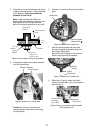
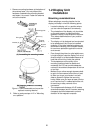
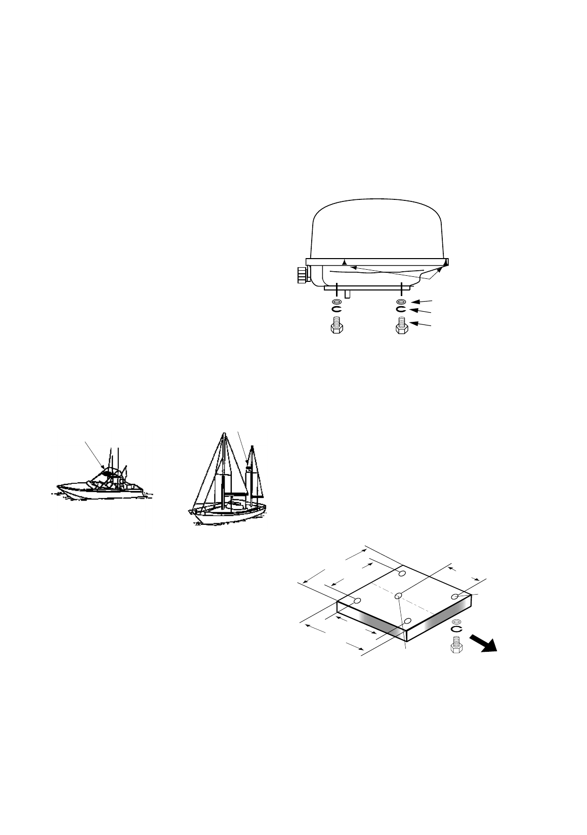
Mounting on a platform
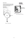
1. Remove mounting hardware at the bottom
of the antenna unit; four each of hex bolts
(M10X20), spring washers and flat washers.
Save mounting hardware to use it to fix the
antenna unit to the mounting platform later
on.
Flat washer
Spring washer
Hex bolt (M10 x 20)
Screws
one screw on other side
Figure 2 Antenna unit, showing location of
mounting hardware
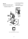
2. Unfasten three screws to remove the cover.
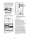
3. Construct a platform (wood, steel, or
aluminum) of 5–10 mm in thickness whose
dimensions are as shown in Figure 4.
Fasten the platform to the mounting
location. Next, position the base so the
cable entrance faces the stern direction and
the vent tube is extending downward
through the hole for the vent tube.
Note:
When drilling holes in the platform, be
sure they are parallel with the fore and aft
line.
160
210
130
160
210
MOUNTING
PLATFORM
(Local Supply)
Hole for Vent Tube
(φ20mm)
Fixing Hole
(φ11mm)
Bow
Figure 3 Dimensions of antenna platform