


4-4
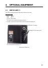
4.2 Connection of Buzzer and/or Remote Display
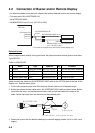
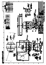
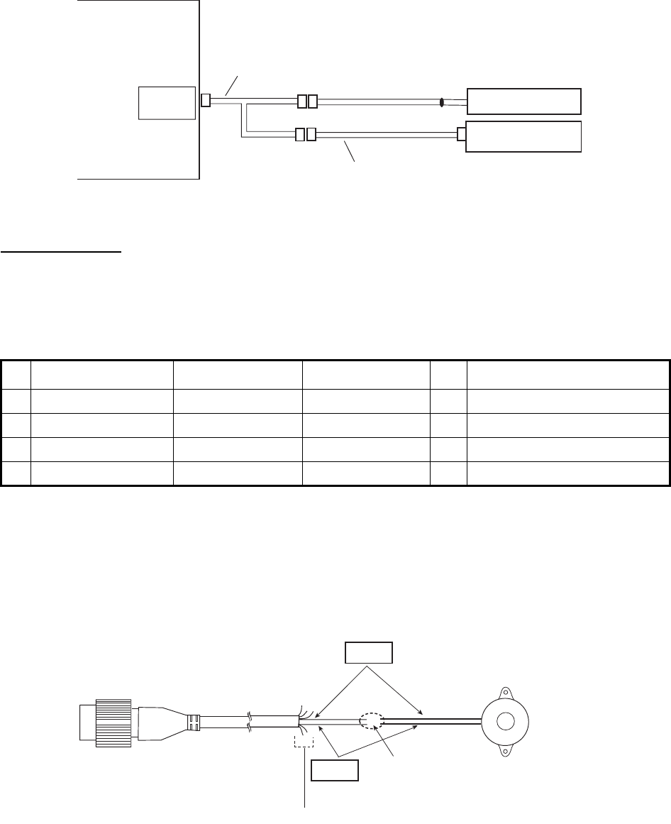
You need the cables shown below to connect the optional external buzzer and remote display.
• Two-way cable MJ-A10SPFW0001+R
• MJ-A7SPF0007-050C
• MJ-B24LPF0010-xxx+R (xxx: 100, 200 or 300)
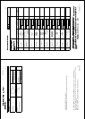
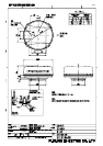
External buzzer
When a target enters (exists) in the guard zone, the optional external buzzer gives a loud alarm.
Type:OP03-21
Code no.:000-030-097
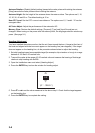
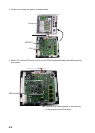
Attach the two-way cable and MJ-A7SPF0007-050C cable to the OPTION port at the rear of the
display unit. See the above figure.
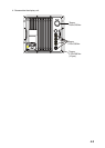
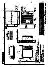
1. Cut the NH connector at the end of the external buzzer cable to an acceptable length.
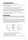
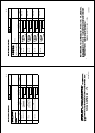
2. Solder the external buzzer cable to the MJ-A7SPF0007-050C cable as shown below. Before
you solder the cores, cut the heat-shrink-tube in half and set the tubes to the cores of the
cable. Solder the cores, then set the tubes on the soldered point.
3. Fasten the buzzer with the double-sided tape or two self-tapping screws (3x15 or 3x20, local
supply).
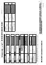
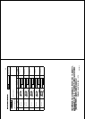
Name Type Code No. Qty Comment
1
Buzzer PKB42SWH2940 000-153-221-10
1
One NH connector attached
2
Cable tie CV-70N 000-162-185-10
4
3
Heat-shrink- tube 3x0.25 BLK 000-165-283-10
1
40 mm
4
Double-sided Tape 9760 000-800-851-00
1
25 mm x 25 mm
OPTION
Remote Display
External buzzer
MJ-A7SPF0007-050C (5 m)
MJ-10P
MJ-10P
MJ-7P
MJB24P
Display unit
RDP-152
Connection Port
MJ-A10SPFW0001+R *
(0.2 m)
MJ-B24LPF0010-xxx+R (10/20/30 m)
(xxx: 100 200 or 300)
*: This cable is not required to connect the remote display only.
Red
Black
External buzzer
MJ-A7SPF0007-050C
Solder
Cut other cables o, and wrap here with tape.