


4. INSTALLING OPTIONAL EQUIPMENT
4-11
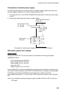
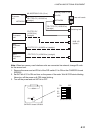
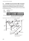
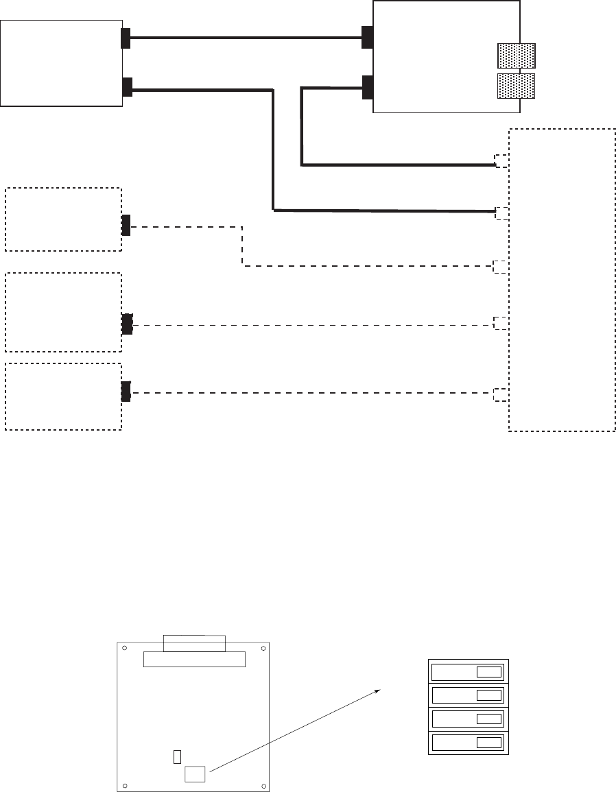
No.1
Processor
unit
J614
NETWORK
No.2
Processor
unit
No.3
Processor
unit
No.4
Processor
unit
MJ-A3SPF0015-100 (10 m)
Memory card IF unit
12 VDC
FR-FTPC-CY (10/20/30 m)
(straight)
FR-FTPC-CY (10/20/30 m)
(straight)
FR-FTPC-CY
(10/20/30 m)
(straight)
FR-FTPC-CY (10/20/30 m) (straight)
FR-FTPC-CY (10/20/30 m) (straight)
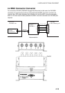
Switching hub
HUB-100
(option)
two mini-cards
NETWORK
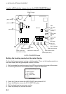
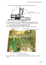
Note: When two memory card interface units are connected via network, change ID code
for the second unit.
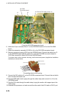
1. Remove the cover and set IP0 bit of the DIP switch S1 to ON on the CARDCPU board
03P9333.
2. Set INIT bit of S1 to ON and turn on the power of the radar. Wait till CR2 starts blinking.
Never turn off the power until CR2 starts blinking.
3. Turn off the power and set INIT bit to OFF.
OFF
ON
(Default: all OFF)
IP0
IP1
IP2
INIT
J314
S1
CARDCPU board 03P9333
CR2