


2. WIRING
2-13
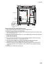
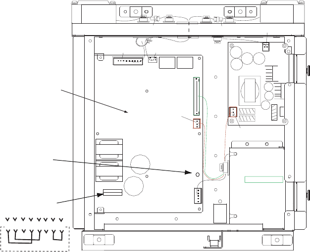
J104
J103
J106
J105
J101
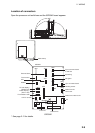
PWR board
(P)HV
AC FIL
P108/J108
R21
(OVER)
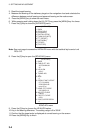
8 7 6 5 4 3 2 1
Jumper connector
(VH8P)
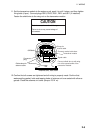
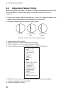
How to adjust the overvoltage detection circuit:
1. Add or remove the jumper connector P108 and change the fuse.
2. Rotate R21 fully clockwise on the PWR board.
3. Connect a variable transformer between ship's mains and the input power terminal board
TB-1 of the processor unit.
4. Adjust the variable transformer output (i.e., input voltage to the processor unit) as follows.
For 100 VAC set: 144 VAC
For 220 VAC set: 288 VAC
5. Turn on the radar and rotate the R21 counterclockwise gradually until the overvoltage
detection circuit functions (i.e., power supply cuts off).
6. Lower the output voltage of the variable transformer and confirm that the radar
automatically turn on with a voltage lower than 142VAC or 284VAC.
7. Gradually increase the output voltage of the variable transformer and confirm that the
overvoltage detection circuit functions at 144V or 288VAC of the variable transformer
output.
8. Assemble and connect the processor unit.