


4. INSTALLING OPTIONAL EQUIPMENT
4-12
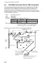
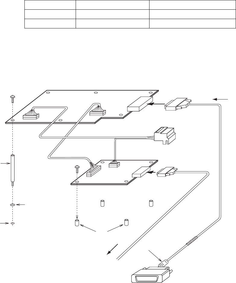
4.3 DVI-RGB Conversion Kit (for VDR connection)
This information provides the procedure necessary for the installation of the DVI-RGB
conversion kit. This kit is installed in the processor unit to enable connection of a VDR
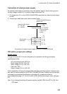
(Voyage Data Recorder) or RGB monitor to record radar pictures into a VDR. When
changing the D-sub 15P of the RGB cable to the BNC connector, use the BNC connector
converter described on page 4-17. This RGB output complies with the image test defined in
the VDR test standard, IEC 61996.
Name: DVI-RGB conversion kit
Type: OP03-180-2
Code no.: 008-536-070
Resolution: Outputs RGB with the resolution of DVI input.
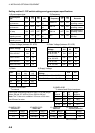
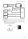
Display unit Resolution DIP switch setting (S-1#1)
MU-201CR 1024x1280 OFF
MU-231CR 1024x1365 ON
Output signal specification: Video; 0.7Vp-p, 75Ω termination, positive polarity
Horizontal sync signal; TTL level, negative polarity
Vertical sync signal; TTL level, negative polarity
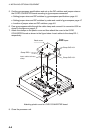
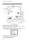
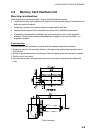
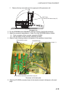
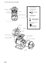
See packing list for contents. Refer to the figure below for modification.
M3x8
4 pcs
SQ-35
Spacer
6 pcs
Fixing
holes
Spring washer
Boss
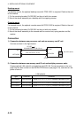
J2
J3
(3 pin)
J1
(13 pin)
J615
J3
J9
(10 pin)
J4
(6 pin)
M3x8
6 pcs
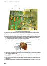
RGB Cable
(User supply)
Clamp copper tape
section by cable clamp.
Ferrite core side: Connect to DVI-D port on
the upper part of the processor unit.
*Indepent of the MAIN board.
DVI cable
03P9342 board
RGB-BUFF board*
(03P9229B)
(SLB-FRN4-A)
DVI-RGB Conversion board
03-2092
03-2094
03-2093
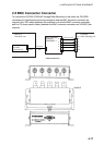
Ferrite core
To external RGB monitor or
BNC connector converter
for VDR connection (see
page 4-17).
D-sub 15P
Female
DVI video input
RGB video output