


2-18
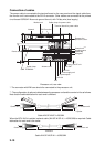
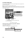
Power supply unit
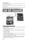
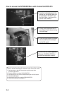
Refer to the illustration and table below to add (or remove) jumper connector P8 from the TX-HV
Board (03P9350) and change fuse.
After completing jumper and fuse arrangements, adjust the overvoltage detection circuit, using a
variable transformer.
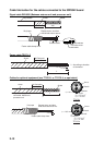
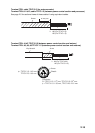
Note: When switching from 220 VAC to 100 VAC, construct a jumper connector locally, referring
to the illustration below. (VH6 connector housing is to be plugged into J8.)
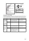
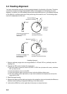
How to adjust the overvoltage detection circuit
1. Add or remove the jumper connector P8 as appropriate and change the fuse, referring to the
table above for details.
2. On the PWR board, set R21 fully clockwise.
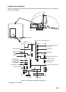
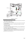
3. Connect a variable transformer between ship's mains and the input power terminal board
TB-1 in the processor unit.
4. Adjust the variable transformer output (i.e., input voltage to the processor unit) as follows:
For 100 VAC set: 144 VAC
For 220 VAC set: 288 VAC
5. Turn on the radar and rotate R21 counterclockwise gradually until the overvoltage detection cir-
cuit activates (i.e., power supply cuts off).
6. Lower the output voltage of the variable transformer and confirm that the radar automatically
turns on with a voltage lower than 142 VAC or 284 VAC.
7. Gradually increase the output voltage of the variable transformer and confirm that the over-
voltage detection circuit activates at 144 V or 288 VAC of the variable transformer output.
8. Assemble and connect the power supply unit.
Power Fuse Jumper connector P8
100 VAC 5A Required
220 VAC 3A Unnecessary
Fuse
TX-HV Board
Unfasten four screws and remove
cover for TX-HV Board.
R21
CR23
P8/J8
6 5 4 3 2 1
Jumper connector
(VH6P)
TB1