


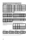
4-14
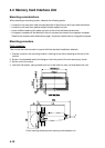
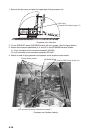
1. Remove the top cover and open the upper part of the processor unit.
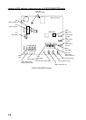
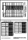
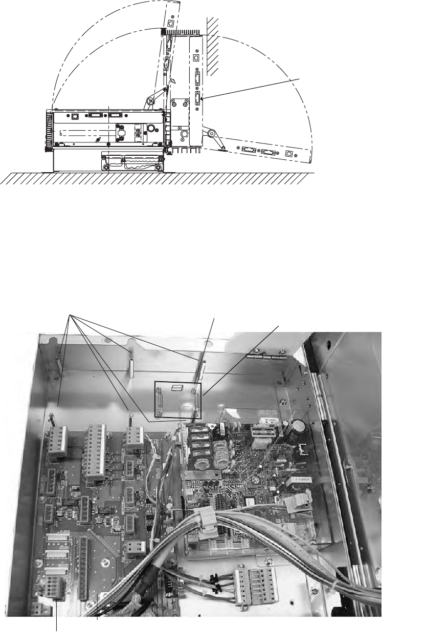
Processor unit, side view
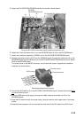
2. Fix the RGB-BUFF board (03P9229B board) with four screws. (See the figure below.)
3. Attach the connector assemblies to J1 and J3 on the 03P9229B board as follows.
J1: 13-pin connector of the connector assembly 03-2094
J3: 3-pin connector of the connector assembly 03-2093
4. Attach six sets of spring washers and spacers at the locations shown below.
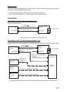
Processor unit (bottom chassis)
DVI-D port
(Connect DVI cable at step 12.)
Spring washer, spacer
03P9229B board
J615 (Connect connector assembies at step 8.)
03P9342 board
J1
J3
J2
J2 (Connect RGB Cable at step 10.)