


2-13
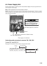
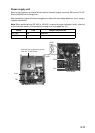
2.5 Power Supply Unit
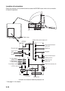
Wire the power supply unit referring to the interconnection diagram. Be sure to ground the unit,
with IV-8sq wire (local supply).
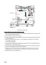
Note 1: Motor specification cannot be changed in the field.
Note 2: Pass the AC line through a double-contact breaker (shipyard supply). Further, for vessels
where the power line is grounded, connect one end of the line to the C (common) terminal and the
other end to the H terminal.
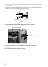
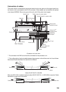
Power supply unit, inside view
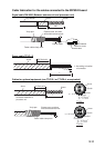
Fabricating cable connected to terminal TB1, TB2, TB3
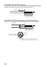
Terminal TB1: cable DPYC-2.5
See page 2-8 for sectional view of cable if using equivalent cable.
TB3: Power output line, control line
Cable clamp: Locate armor of cables in clamp.
TB1, TB2: Power input line
Ground
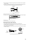
High voltage is present at the
No. 6 pin of TB3. Miswiring at
this pin can damage the unit.
CAUTION
30: Remove paint.
Armor
120
FV2-4