


Contextual Menu
1 2 3 4
1
2
3
4
5
5
6
6
7
7
8
8
9
9
10
10
10
11 11
11
Press “EBL 1” and “EBL 2” to activate/deactivate respective EBL;
and rotate the encoder to adjust active EBL.
Rotate to adjust brilliance level of the FURUNO monitor; and
press to select display palette.
Press “VRM 1” and “VRM 2” to activate/deactivate respective
VRM; and rotate the rotary encoder to adjust active VRM.
Rotate to select items within the
I.A.bar; and press to confirm the
selection of the item.
Full QWERTY keyboard for easy entery of route, event and
waypoint names.
Following functions are assigned for each key:
UNDO: to undo the last operation
RANGE: to select chart scale
Following functions are assigned for each key:
VIEW/HIDE: to show/hide the I.A. bar and route information window
ACQ/ACT: to activate selected active AIS target
TARGET DATA: to display the detailed target data for selected TT/AIS
TARGET CANCEL: to sleep the selected active AIS target
USB port for charts update, import/export, WP/routes, user setting.
Trackball Module
Trackball module consists of four parts, each of which has the following functions:
trackball: to move the cursor and select an object
left-click: to perform/confirm the action related the selected object
right-click: to display contextual menu while a cursor is on the display area, and to
cancel action done on the selected object
scrollwheel: to select menu items
For acknowledgement of alerts generated.
Rotate to adjust radar gain on the radar overlay.
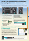
FURUNO’s new user interface delivers straightforward,
task-based operation
FURUNO’s new user interface delivers straightforward,
task-based operation
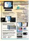
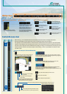
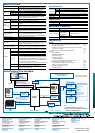
ECDIS Control Units
The operator control of the FMD-3200 and FMD-3300 can be done with the ECDIS Control Unit RCU-024 or the Trackball Control Unit RCU-026.
All functions of the ECDIS can be accessed by using the trackball, scrollwheel and left/right clicking.
InstantAccess bar
The user interface of the FMD-3200/FMD-3300 centers on carefully
organized operational tools: Status bar and InstantAccess bar.
The Status bar at the top of the screen contains information about the
operating status, i.e., MFD operating mode, the ECDIS operation
modes, etc. InstantAccess bar at the left-hand side of the screen
contains all the tasks (functions/actions) corresponding to the ECDIS
operation mode currently selected. These operational tools deliver
straightforward, task-based operation by which the operator can quickly
perform navigational task without having to go deeper into an intricate
menu tree.
Task-based user interface realized by combination of Status bar and
InstantAccess bar providing quick access to
the needed tasks/functions
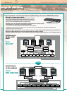
Drop-down menu to facilitate streamlined operation
Click to open
on buttons in the Status bar and InstantAccess bar indicate that
there are hidden options of actions/tasks to be performed in the
sub-layer, which can be initiated by left-clicking the buttons.
This way, the operator can quickly gain access to the related tasks.
Right-clicking on the screen will open the contextual menu
containing all the available actions related to the position of
the cursor, i.e., chart object, data box, etc., hence providing
quick access to tasks required.
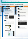
Items on the upper part of the InstantAccess bar:
Monitor Mode
In the Monitor Mode, ship’s behaviour can be monitored in
relations to the planned route. Various voyage monitoring
tools are incorporated into the InstantAccess bar.
Chart Maintenance Mode
The Chart Maintenance Mode allows the operators to
handle charts to be used in the system
Plan Mode
In the Plan mode, the operators can generate and edit route plans as well as user charts. Also, various detailed
reports, generated by ECDIS, on planned routes as well as user charts can be
viewed. All these tasks can be accessed from the InstantAccess bar.
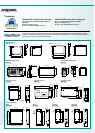
ECDIS Control Unit RCU-024 Trackball Control Unit RCU-026
Status bar
InstantAccess bar
1
2
3
9
10
11
12
A guide box instantly
tells the operators the
range and bearing
between the last
waypoint and the
cursor position as you
drag the cursor.
Click to open the data management windows for
routes as well as user charts where selected
routes and user charts can be deleted.
Creating User Chart:
When clicking on “User chart”, user chart tools
(a palette and a menu window) will be displayed
by which operators can create a user chart.
A user chart is a layer consisting of marks and
lines that can be produced and overlaid onto the
chart. It is intended for indicating safety-related
areas and objects.
Quick access to various reports:
Route reports on waypoints and passage plan
as well as user chart reports on tidals, lines,
user-entered objects and user-dened areas
can be directly accessed for viewing from the
InstantAccess bar.
Route Planning Dialog Box
Route Planning Display
User Chart Tools
Route Planning:
Once left-clicking on “Route”, a route planning menu
window will open. The operators can use the trackball
to enter waypoints directly onto the chart. After entering
a waypoint, the operators can edit name, steering
mode, radius, channel limit and other parameters of the
waypoints on the menu window.
9
12
11
10
4
5
6
7
8
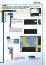
chart license menu window
Click to start automatic installation of the chart data from
the chart CD or DVD ROM.
Click to manage charts, i.e., grouping chart cells by
purposes, deleting unnecessary chart cells, etc.
Click to view the chart catalog that shows general
information about the charts installed in the system, i.e.,
coverage, license status, availability and other status
information.
Click to open the chart license menu window where the
operators can view the permit status of the chart installed.
Also, the operators can install, backup, restore and export
the chart licenses from the same menu window.
Click to open Public Key management window.
This allows user to change the Public Keys which are
used to authenticate the source and integrity of the chart
materials used in ECDIS.
4
5
6
7
8
Select:
Click to open route selecting menu window to select
the route to monitor.
Unselect:
Click to stop monitoring the route.
Move to plan:
Click to transfer the route currently being
monitored to the Plan Mode in order to amend the route.
Route INFO:
Click to open the route information window
where the detailed parameters set for each waypoint within the
route as well as the details of the user chart can be veried.
Also, notes/cautions on status of the monitored route as well
as user chart can be viewed.
Click to open the
AIS/NAVTEX message
menu window from which
the operators can handle
AIS/NAVTEX messages,
i.e., sending, viewing and
deleting the messages.
Click to open the manual update menu window by which the
operators can update the electronic chart by inserting chart
update symbols manually, according to the Notices to
Mariners, NAVTEX warnings, etc. Manual update of the chart is
required to ensure that the chart is kept up to date at all times.
When the ofcial chart update containing the changes by the
manual update is made, the operator can delete the manual
update symbols through the manual update menu window.
AIS/NAVTEX message dialog box
1
2
3
Route monitoring
Radar overlay
Route planning