


GMR 20/40 Radar Installation Instructions
3
Mounting the Scanner
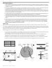
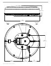
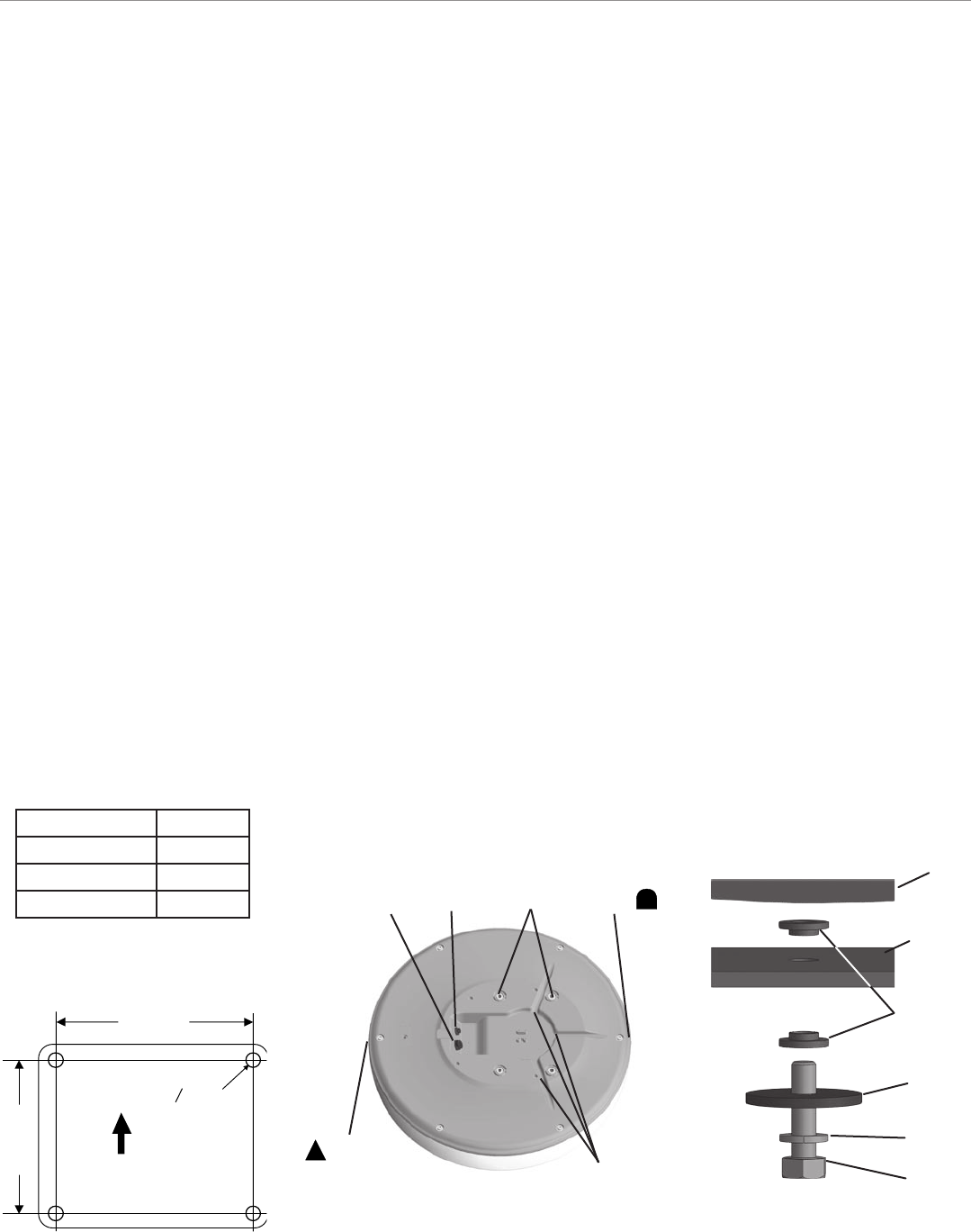
1. Once a suitable mounting location has been determined, verify that the mounting hole locations are aligned fore and aft, then drill four
9.5 mm (0.37") mounting holes referencing Figure 1 below. (This step is not necessary if you are using a pre-drilled Garmin compatible
or Raymarine mount.)
2. Remove the supplied M8x30 bolts, flat washers, and spring washers (4 each) from the bottom of the scanner unit. Do NOT remove the
outer case bolts. There are no user serviceable parts in the scanner and opening the case may void your warranty.
3. Align the notch and locking ring on the Power Cable to the power connector. Press the 2-pin Power Cable to the power connector and
the RJ-45 Marine Network Cable to the RJ-45 socket (Figure 2). Turn the Power Cable locking ring clockwise until it stops. Tighten the
RJ-45 locking ring clockwise until it is firmly sealed.
4. The Power/Network Cable may be pressed into one of the three guide grooves moulded into the bottom of the scanner case (Figure 2).
Avoid excessive bending or twisting of the cable. See the following “Cable Runs” section for more information.
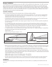
5. Position the scanner on the mounting surface with the triangular marks on the case aligned to the front of the vessel and the rounded
marks aligned towards aft (Figure 2). A bead of marine sealant may be applied around each of the mounting holes on the mounting
surface.
6. Fasten the scanner to the mounting surface using the M8x1.25x30 hex bolts, spring washers, and flat washer and shoulder washers
in the order show in Figure 3. The supplied M8x1.25x30 bolts, flat washers, and spring washers (4 each) may be used on mounting
thicknesses of 5-10 mm (3/8") (recommended). For surfaces over 10 mm (3/8"), locally supplied longer bolts are needed. The bolts
should be torqued to between 13.7-18.6 N m (10-14 lb ft).
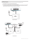
Cable Runs
Route the cable as needed, depending on the type of mount you are using. Do NOT cut the cable! It may be necessary to drill a 31.7 mm
(1.25") hole for routing the Power/Network cable. Garmin provides a rubber Cable Grommet which may be used to cover the cable installation
hole. The grommet does NOT provide a waterproof seal. You may choose to apply a marine sealant after installation to weatherproof around the
grommet and cable. Additional Cable Grommets may be purchased through Garmin or your Garmin dealer.
When installing the Power/Network Cable, observe the following:
• To ensure safety, use the appropriate tie-wraps, fasteners, and sealant to secure the cable along a route and through any bulkhead or deck.
Avoid running the cable near moving objects, high heat sources, or through doorways and bilges.
• Avoid installing the cable next to or in parallel other cables such as, radio antenna lines or power cables. This is essential to avoid
interference to/from other equipment. If this is not possible, shield the cable with metal conduit or a form of EMI shielding.
• Install the Power portion of the cable as close to the battery source as possible. A minimum of 10 v D.C. is required at the 15 m cable
connector during radar turn-on and operation. See table below for recommended wire gauge between radar cable and battery.
Ship's Bow
141.5 mm
(5.57")
233.0 mm
(9.17")
O 9.5 mm
(0.37")
Figure 3
Mounting
Bracket
Flat
Washer
Spring
M8x30
Bolt
Figure 2
Mounting
Holes
Power
Connector
Network
RJ-45 Port
Bow
Mark
Stern
Mark
Cable Guide
Grooves
Figure 1
Wire Gauge Table
Up to:
2 meters (6.5 ft) 16 AWG
4 meters (13 ft) 14 AWG
6 meters (19 ft) 12 AWG
Shoulder
Washer
Scanner