


4
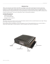
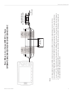
GSD 20 Sonar Module
INSTALLATION INSTRUCTIONS
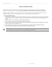
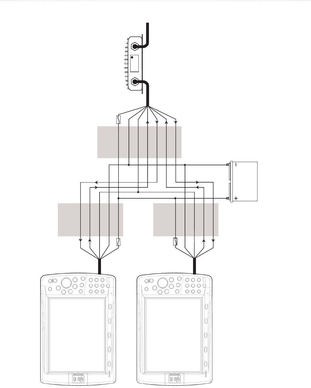
BATTERY
10-35 VOLTS DC
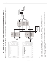
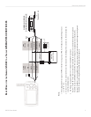
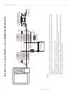
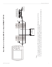
BASIC WIRING FOR THE GARMIN GSD 20 TO A DUAL GPSMAP 2006/2006C/2010/2010C
*This diagram does not apply to the GPSMAP 3005C/3006C/3010C. Refer to Note 4 on the Single GPSMAP
2006/2006C/2010/2010C/3005/C3006C/3010C diagram.
Notes:
1. Power and ground wires require 18 AWG. All other wires require 22 AWG. Use 4-conductor, shielded wiring for runs over 30’ (9.1 m).
2. Refer to the GPSMAP 2006/2006C/2010/2010C Installation Instructions for wiring the GPS 17 sensor and other devices.
3. For runs over 30’ (9.1 m), the drain wire must be connected to the shielding of the extension run. Do not terminate the end of the shield drain wire.
4. Use unit #1 to update the GSD 20 software.