


6
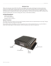
GSD 20 Sonar Module
INSTALLATION INSTRUCTIONS
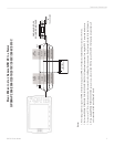
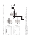
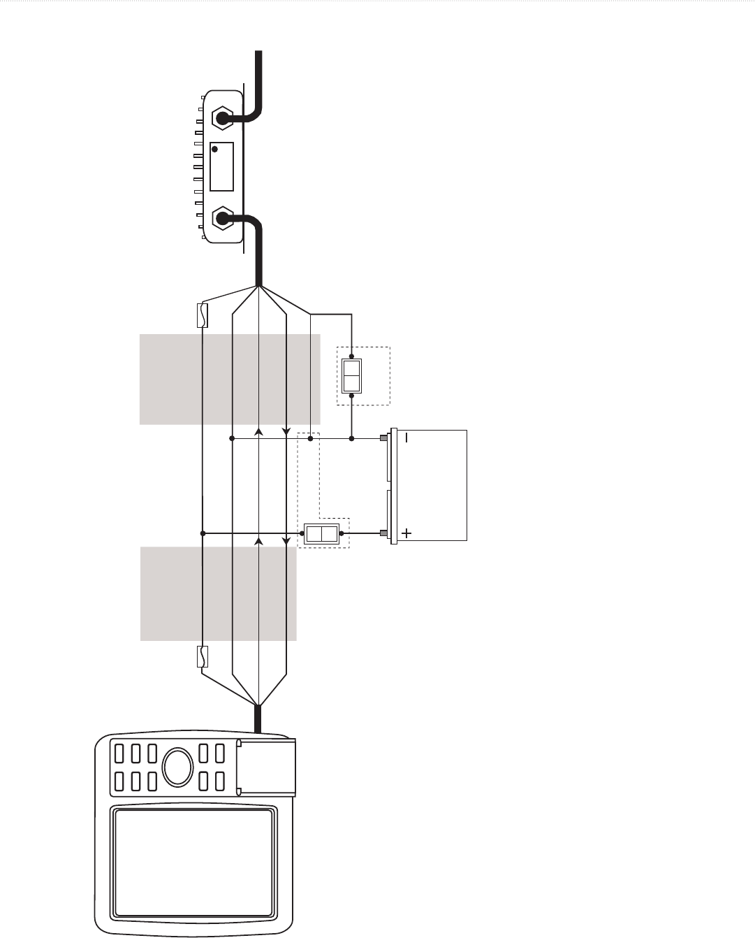
BASIC WIRING FOR THE GARMIN GSD 20 TO A SINGLE GPSMAP 182/182C/192C/232
WIRE
COLOR
GARMIN GSD 20
SOUNDER MODULE
BLACK
ORANGE
RED
WHITE/BLUE
BLACK
RED
BLUE
BROWN
WHITE/BROWN
WIRE
COLOR
FUSE
1.5A
FUSE
2A
TO
TRANSDUCER
ON
OFF
SEE NOTE 3
OPTION 1
BATTERY
10-35 VOLTS DC
ON
OFF
SEE NOTE 3
OPTION 2
Notes:
1. Power and ground wires require 18 AWG. All other wires require 22 AWG. Use 4-conductor, shielded wiring for runs over 30’ (9.1 m).
2. For runs over 30’ (9.1 m), the drain wire must be connected to the shielding of the extension run. Do not terminate the end of the shield
drain wire.
3. The Orange wire must be pulled low (-) in order for the GSD 20 to power on.
Option 1: If the GSD 20 is wired to a circuit that is switched on the Red (+) wire, connect the Orange wire to ground. The GSD 20 and
the GPSMAP 182/182C/192C/232 turns on/off when power is applied/removed to the Red wire.
Option 2: If the Red (+) wire is applied directly to a power source, install a switch between the Orange wire and ground. The GSD 20
turns on or off when ground is applied or removed to the Orange wire.