


Introduction
This guide describes the operation of the Apollo SL40
VHF Communication Transceiver.
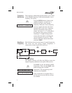
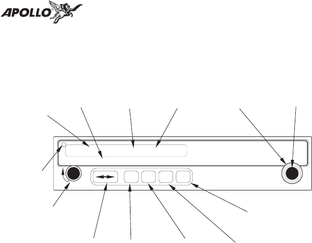
Display
The 1-line by 16-character display is composed of 5x7
dot matrix alphanumeric high intensity LEDs. A
photocell is located in the top left corner of the front
panel display. The photocell automatically controls the
intensity of the display from low brightness at night to
high brightness during daylight operation. Brightness
levels may also be controlled manually.
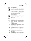
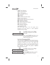
Annunciators Several annunciators are used to help indicate the
operating modes of your Apollo SL40. The TX
(Transmit) annunciator is lighted whenever you are
transmitting. If the avionics bus drops below 9 VDC, the
SL40 will not transmit. An LED will be lighted above
the MON and RCL buttons when these functions are
selected. An “s” will appear to the left of the Standby
frequency. An “m” will appear to the left of the Standby
frequency when you are using the Monitor function. An
“I” indicates the Intercom function is being used.
TX - Transmit
s - Standby Frequency
m - Monitor Mode
I - Intercom
1
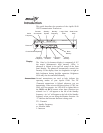
EC RCL
MON MEM
TX
POLLO
A
SL40
COM
PULLSQUELCH
VOL
OFF
119.80 s121.50
Power/Volume/Squelch
Photocell
Active
Frequency
Standby
Frequency
Flip/Flop
Frequency
Emergency
Channel
Store
Memory
Recall
Memor
y
Frequency
Monitor
Large, Outer
Knob
Small, Inner
Knob
Transmit
Annunciator
Standby
Symbol