


K177 Issue No. 3
6 RPT 301 User Manual
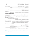
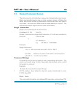
Power supply
The instrument is internally fused with reverse polarity and overvoltage protection.
Note: The power input is transformer isolated from the logic circuits and the
serial data link. The isolation voltage is 50V dc.
For continuous operation the ‘Start-up’ connections should be connected to the
supply, make sure the polarity is correct and the current requirements are met.
When RS232 is used, the RTS line can be connected to the `Start-up' input and
the RTS input on pin D so that the control computer can turn on the instrument.
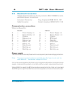
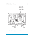
2.3 Electrical Connection
The electrical connector is a 10-way connector (MIL C26482) for serial,
parallel and power connections.
Instrument Connector - Plug, Amphenol 62GB 12E12 - 10P
Cable Connector - Socket, Amphenol 62GB 16F12 - 10S
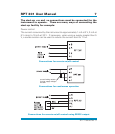
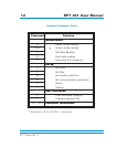
Communication connections
When configured for:
RS485
A = Power Supply -ve
B = Power Supply +ve
C = Chassis
D = Data out +ve
E = Data out -ve
F = Data In +ve
G = Data In -ve
H = Data Ground
J = Start-Up -ve
K = Start-Up +ve
RS232
A = Power Supply -ve
B = Power Supply +ve
C = Chassis
D = RTS Input
E = Data Out
F = CTS Output
G = Data In
H = Data Ground
J = Start-Up -ve
K = Start-Up +ve