13
308485
Air Motor and Throat Service
12. Slide the piston rod (29) down through the pack-
ing, and lower the piston (27) into the air motor
base (28).
13. Clamp the air motor base (28) in a vise horizontally
by closing the vice jaws on the flange.
14. Install the u-cup packing (107{) with the lips up,
and place the piston washer (113) on the piston/
valve seat (109).
NOTE: Make sure the lips of the u-cup packing
(107{) face up. See Fig. 3.
15. Place the piston ball (103) in the piston rod (29).
16. Apply Loctiter to the threads of the piston/valve
seat (109), and thread the assembly from Step 14
onto the piston rod (29).
17. Clamp the flats of the piston/valve seat (109) in a
vice, and, using a crow’s-foot wrench, torque the
piston rod (29) to the piston valve seat to 40 to 60
ft-lb.
18. Clamp the air motor base (28) in a vise horizontally
by closing the vice jaws on the flange
19. Use a strap wrench to screw the displacement
pump cylinder (110) to the air motor base (28), and
torque with a crow’s-foot wrench to 95 to 105 ft-lb.
20. Before remounting the pump, connect an air hose
and run the air motor slowly, at about 40 psi (0.28
MPa, 2.8 bar) to see that it operates smoothly.
21. Reconnect the ground wire before regular opera-
tion of the pump.
Displacement Pump Service
Disassembly
NOTE: Displacement Pump Repair Kit 237602
includes repair parts for the pump throat and
piston. Use all the parts in the kit for the best
results. Parts included in the kit are marked
with a dagger, for example (7{), in the text and
drawings. See the Parts List on page 16.
1. Flush the pump. Follow the Pressure Relief
Procedure on page 8, before proceeding.
2. Disconnect the hoses, remove the pump from its
mounting, and clamp the air motor base (28) in a
vise horizontally by closing the vice jaws on the
flange.
Intake Valve See Fig 5.
1. Follow the Pressure Relief Procedure on
page 8.
2. Unscrew the valve housing (111). Remove the
o-ring (105{), retainer (112), and ball (104).
3. Inspect the parts for wear or damage. If the ball is
nicked, replace it. Reassemble, using grease on
the male threads.
Displacement Pump See Fig 5.
NOTE: Clean and inspect all parts for wear or damage
as you disassemble them. Replace parts as
needed. For best results, always replace all
the o-rings and packings when you disassem-
ble the pump.
1. Follow the Pressure Relief Procedure on
page 8.
2. Follow steps 1 through 6 of Disassembly on page
10.
3. Carefully inspect the smooth, inner surface of the
cylinder (110) for scoring or irregular surfaces.
Such damage causes premature seal wear and
leaking. Replace the cylinder as needed.
Reassembly
Do steps 14 through 21 in Air Motor and Throat
Service on this page.
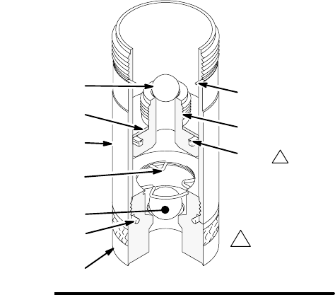
Fig. 5
104
111
105{
1
03847
110
107{
112
1
108{
109
103
113
Lips face up
{ Included in Repair Kit 237602.


