5
308485
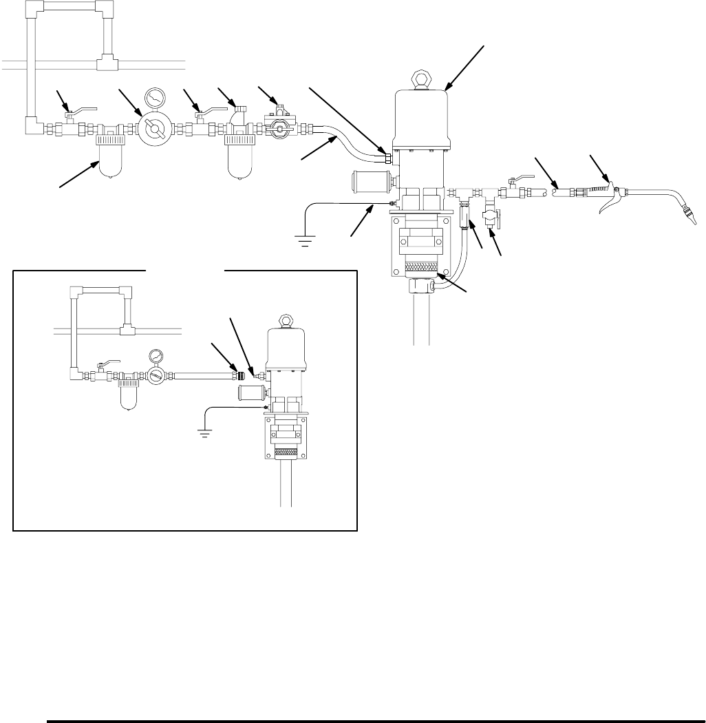
Installation
The typical installation shown in Fig. 1 is only a guide for selecting and installing a pump; it is not an actual system
design. Contact your Graco representative for assistance in designing a system to suit your needs.
DN
A
C
A
KEY
A Bleed-type master air valve (required)
B Air line filter
C Air regulator and gauge
D Pump runaway valve (shown for
position) not needed if you use
a low-level cut-off valve
E Air Inlet
G Pump (Model 237526 shown)
H Fluid drain valve (required)
J Dispensing valve (Model 222411 shown)
K Thermal relief kit (required) 237601
L Male quick-disconnect fitting
M Female quick-disconnect coupler
N Air line lubricator
P Fluid hose
S Fluid inlet, 1 1/2” npt
R Electrically conductive air hose (218093 shown)
Y Ground wire (required)
Fig. 1
B
E
G
Y
H
P
J
L
M
DETAIL A
For portable applications
R
S
K
06025


