


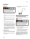
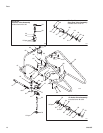
Installation
8 306556S
All Models
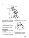
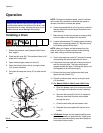
Refer to F
IG. 7 for the following Steps.
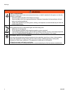
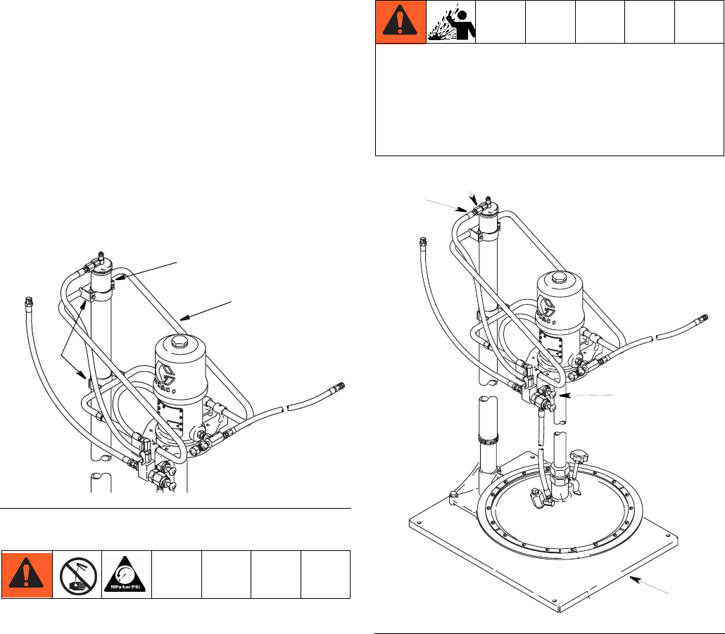
4. Loosen the pump support clamps again and raise
the support (64) until it meets the pump base.
5. Secure the President or Fire-Ball pump to the pump
support mounting plates from the underside with the
screws (68).
6. Tighten screws (68) on lower pump bracket (83).
7. Slide the upper support bracket (83) up or down (the
tubing of the pump support (64) will flex slightly)
until the pump is in a true vertical position.
8. Tighten the screws (68) on the upper bracket.
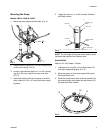
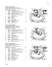
Installing the Hoses and Valves
NOTE: Use thread sealant on all male threads except at
the swivel unions.
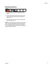
1. Remove the plug from the top of the elevator cap
and screw it into the air inlet (E) in the elevator base.
(F
IG. 8)
1. Screw the restrictor valve assembly (42) into the
elevator cap.
2. Screw the 1/4 x 1/8 npt adapter (85) into the restric-
tor valve. (F
IG. 8)
3. Install the 1/4 x 3/8 npt adapter (89). (F
IG. 8)
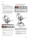
4. Connect one end of the 36 in. (914 mm) hose into
the adapter and the other hose end into the
snap-over valve’s (27) union (82). (F
IG. 8)
5. Route the hose inside the arms of the pump support
(64). (F
IG. 7)
6. Screw the hex nipple (115 or 99) from the outlet
hose kit (91 or 97) to the pump outlet. (See Parts
Drawing on Page 16.)
7. Connect the kit’s swivel union (96) to the adapter
with the opening in the valve (94) facing down. (See
Parts Drawing on Page 18.)
FIG. 7
83
64
68
The bleed-type master air valve is required in your
system to relieve air trapped between this valve and
the pump after the air is shut off. Trapped air can
cause the pump to cycle unexpectedly and cause
serious injury, including splashing in the yes or on the
skin. Position the valve close to the pump.
FIG. 8
E
85
89
27