Repair
12 3A1211M
Repair Air Motor
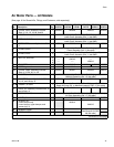
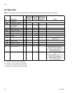
NOTE: Air Motor Seal Kits are available. See page 17
for the correct kit for your motor. Parts included in the kit
are marked with an asterisk (*). For best results, use all
the parts in the kit.
Preliminary Steps
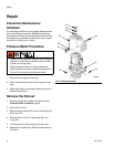
1. Stop the pump at the middle of its stroke. Follow
Pressure Relief Procedure, page 8.
2. Disconnect air lines.
3. See Remove the Shroud, page 8.
Disassemble the Air Motor
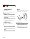
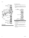
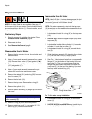
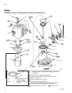
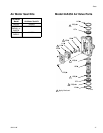
1. Remove the tie rod nuts, tie rods, tie rod plate, and
bottom shroud.
2. Use a 10 mm socket wrench to remove four screws
(18). Remove the air valve (17) and gasket (16*◆).
3. Remove four screws (18) and remove the manifold
(15*) and gasket (14*).
4. Use a 10 mm socket wrench to remove the pilot
valves (19) from the top and bottom cover.
5. Remove the adapter (31) and o-ring (32) from cen-
ter of top cover (13).
6. Remove the tie bolts (10).
7. Remove the top cover. Remove the o-ring (9*).
8. Remove the cylinder (11).
9. Slide the piston assembly (5) straight up off the bot-
tom cover.
10. Remove o-ring (8*) from around the piston.
11. Remove retaining ring (4*), u-cup seals (3*, 33*),
and o-ring (9*) from the bottom cover.
Reassemble the Air Motor
NOTE: Use NLGI No 1, bentone-based grease for lubri-
cant. Exception: Use appropriate sanitar y lubricant for
the center grommet in the bottom shroud.
NOTE: For easier reassembly, start with the top cover
(13) turned over on the workbench and assemble the air
motor upside-down.
1. Lubricate and install the o-ring (9*) on the top cover
(13).
2. 24G787 only: Install the upper bumper (29) on the
top cover (13).
3. Lubricate the inside of the cylinder (11). Lower the
cylinder (11) onto the top cover (13).
4. Lubricate and install the o-ring (8*) around the pis-
ton (5).
5. Slide the piston assembly (5) down into the cylinder
(11). Be sure the o-ring (9*) stays in place.
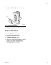
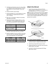
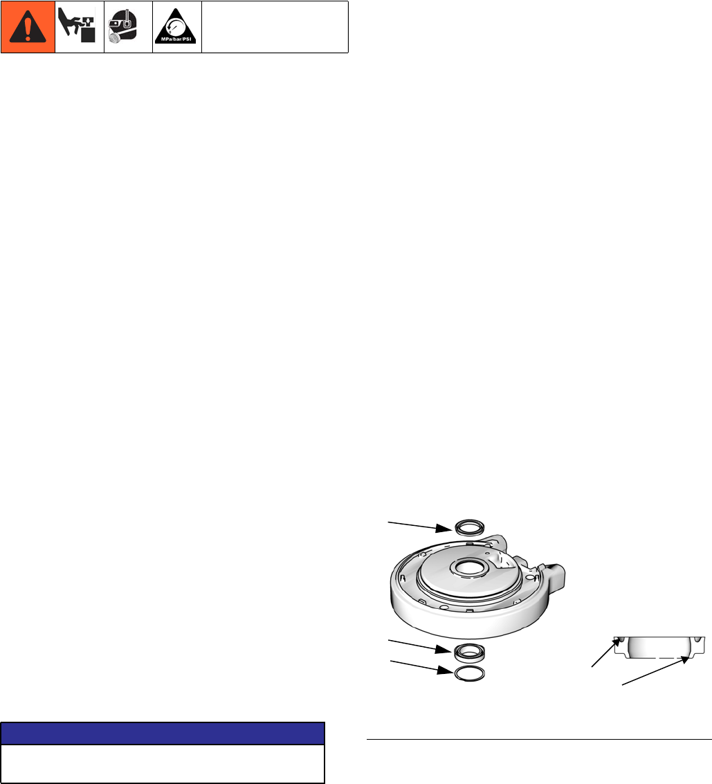
6. See FIG. 7. Lubricate and install new u-cup seal with
flange (33*) in the bottom of the bearing in the bot-
tom cover (1). The u-cup must face up and the
flange must face down. Lubricate and install new
u-cup seal (3*) in the top of the bearing. Lips must
face up. Install retaining ring (4*).
7. Lubricate and install the o-ring (9*) on the bottom
cover (1).
8. 24G787, 24G786, and 24W754 only: Install the pis-
ton bumper (28) on the bottom cover (1).
NOTICE
To prevent damage, do not attempt to take apart the
piston assembly (5).
FIG. 7. Air motor u-cup installation
3*
33*
ti12755a
U-cup faces up.
Flange faces down.
Lips face up
4*


