


Repair
3A1211M 13
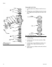
9. Carefully place the bottom cover (1) on the cylinder
(11), sliding the rod through the bearing. The mani-
fold surfaces of the top and bottom covers must
align.
10. Install the tie bolts (10) hand tight.
11. Install two gaskets (14*) on the manifold (15). Install
the manifold (15). Torque bolts to 95-105 in-lb
(10.7-11.9 N•m).
12. Align the air valve gasket (16*◆) on the manifold,
then attach the air valve.
13. Tighten the tie bolts (10) halfway. Work in a criss-
cross pattern. Continue tightening the bolts in pat-
tern to the torque specified in the following table.
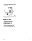
14. Lubricate and install pilot valves (19) in top and bot-
tom cover. Torque to 95-105 in-lb (11-12 N•m).
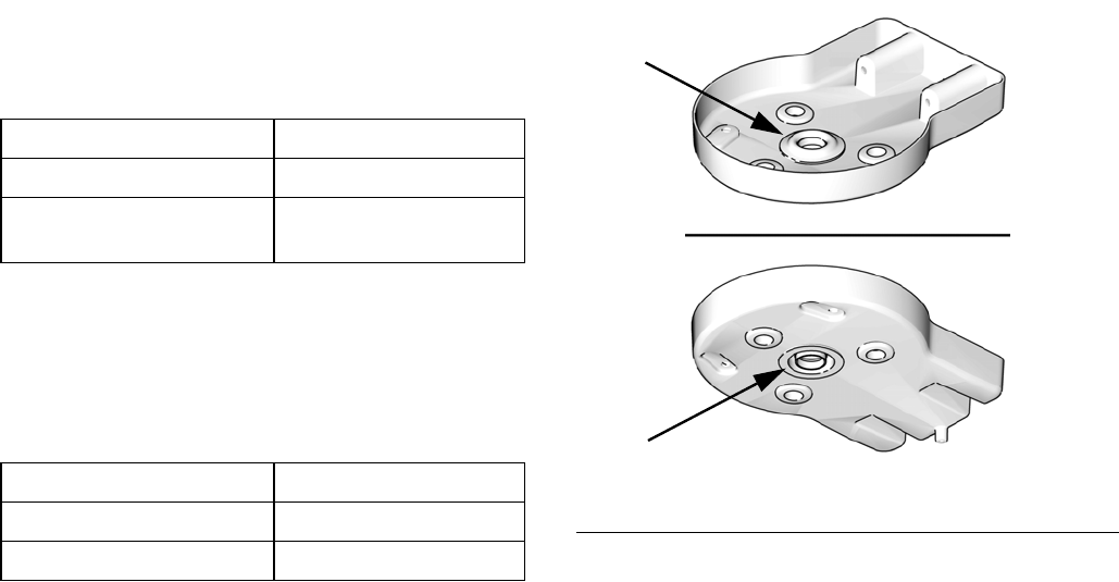
15. Install the adapter (31) and o-ring (32) in the center
of the top cover (13). Lubricate or apply sealant to
the o-ring as specified in the following table.
Attach the Shroud
1. Inspect the grommets on the top and bottom
shrouds. Order Kit 16G628 (for 3.5 in. air motors) or
Kit 16G385 (for 6.0 in. or 7.5 in. air motors).
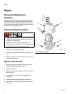
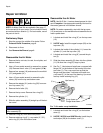
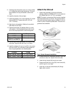
NOTE: The piston rod grommet (21a) must be installed
with the flat side down, as shown. The grommet will be
flush with the shroud when properly installed. It will not
remain in place if installed upside down. The other two
grommets are reversible.
2. If bottom shroud (47) has been removed, slide it up
onto the tie rods (10). Tighten the screws (48).
3. Lower the top shroud (46) over the air motor.
4. Grease and install the o-ring (39), hand screw (40),
and lift ring (41), hand tight.
5. Install the air inlet (43) and exhaust (42) fittings
tightly with a wrench.
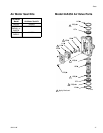
Air Motor Torque
24G785
11-13 ft-lb (15-18 N•m)
24G786, 24G787, 24R491,
24R015, and 24W754
25-30 ft-lb (34-40 N•m)
Air Motor O-Ring
24G785, 24G786, 24G787
PTFE; apply sealant.
24R491, 24R015, 24W754
Buna-N; apply lubricant.
FIG. 8. Center Grommet Installation
ti12755a
21a
21a