


12 307212
Service
Service of the Air Operated Regulators
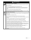
WARNING
To reduce the risk of serious injury whenever you
are instructed to relieve pressure, always follow the
Pressure Relief Procedure on page 8.
1. Shut off the pump.
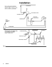
2. Close the ball valve at the regulator’s air inlet.
Refer to Fig. 2.
3. Release all the air and fluid pressure in the regula-
tor and disconnect the air and fluid lines.
4. Remove the regulator from the system.
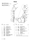
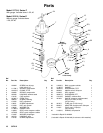
5. Remove the swivel union (23) and spring (40) from
the regulator body.
6. Remove the ball (20), seat (16), and gasket (15).
See Fig. 4.
CAUTION
Use special care when handling the hard carbide ball
(20) and seat (16) to avoid damaging them.
NOTE: Gasket (15) is thin and translucent. Be sure to
remove the gasket.
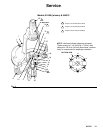
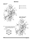
7. Remove the six cap screws (1) and housing (6).
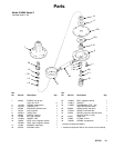
8. Place diaphragm assembly in a vise, with jaws on
stem housing (18). Remove the retaining screw
(10), jam nut (13) and washer (17) from the stem
housing (18).
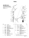
9. Remove the diaphragm (22) and gasket (26).
10. Remove the spring (3), valve stem (9), and gasket
(21) from the stem housing (18).
11. Thoroughly clean and inspect all parts. Replace
any parts that appear to be worn or damaged.
12. Place stem housing (18) in a vise. One at a time,
place the gasket (26), diaphragm (22) – white
PTFE side down toward the bottom housing, and
washer (17) on the stem housing (18). Secure
them with the jam nut (13). Torque the jam nut
onto the stem housing to 21–35 ft-lb (28–47 NSm).
13. Install the valve stem (9), spring (3), gasket (21),
and retaining screw (10) in the stem housing (18).
Make sure the tab on the valve stem (9) fits into
the slot on screw (10).
14. Torque the retaining screw into the housing to
21–25 ft-lb (28–34 NSm).
15. Install the assembled parts in the housing (6).
16. On Model 214980, tighten the air line fitting (29)
into the cap (7). Torque to 21–35 ft-lb (28–47
NSm).
17. Install the cap (7). Tighten the six cap screws (1) in
the sequence shown in Fig. 4, Bottom View, and
to the torque noted.
18. Install the gasket (15), valve seat (16), and ball
(20) into the housing (6).
NOTE: Seat may be turned upside down and reused.
19. Screw the swivel union (23), with the o-ring (4)
attached and the spring (40) in place, into the inlet.
Torque to 23–27 ft-lb (31–36 NSm).