


Repair
4 312068M
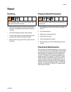
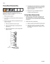
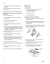
Pumpline Disassembly
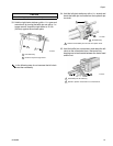
1. Remove plug fitting (206) from lube cylinder (205).
2. Insert clevis pin removal tool 296607 through open-
ing in lube cylinder (205) and screw tool into left
clevis pin (219). Pull clevis pin out of clevis (117).
3. Use hex key to remove four socket head cap
screws (203) from left proportioning pump (202).
Remove left proportioning pump.
4. Remove lube cylinder (205).
5. Screw pin removal tool 296607 into right clevis
pin (219). Pull clevis pin out of clevis (117).
6. Use hex key to remove four socket head cap
screws (203) on right proportioning pump (202).
Remove right proportioning pump.
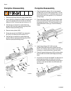
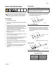
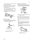
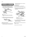
Pumpline Reassembly
1. Slide the hydraulic piston (104) in the hydraulic
cylinder (201) out to its left-most position. The left
end of the left clevis (117) should be nearly in line
with the left end of the spacers (113). See the fol-
lowing image.
2. Place hydraulic cylinder (201) on flat surface with
both the manifold (125) and the port blocks (116)
contacting the surface. The two main ports in the
manifold should be facing up. See the following
image.
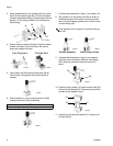
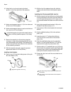
3. Install elbow fittings (207, 208) into lube
cylinder (206) and install lube cylinder over left
clevis (117). Ensure clevis pin hole in lube cylinder
is vertical, in line with the hole in the left clevis.
4. Place left proportioning pump (202) on flat surface
with the wide end of the outlet flange (26) facing
down.
5. Use clevis pin removal tool 296607 to slide the pro-
portioning pump piston rod (28) out to its limit.
Ensure the hole in the proportioning pump shaft is
vertical, in line with the hole in the left clevis and
lube cylinder.
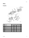
203
202
207
204
205
206
204
202
203
219
201
219
ti13870a
208
ti13871a
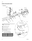
125
116
116
113
104
117
ti13875a
28
206
35
26