


Setup
4 312497P
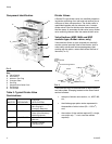
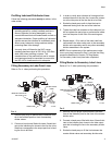
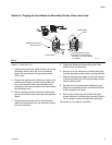
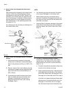
Component Identification
Key:
A Valve Section
B Inlet Section
C Indicator / Port Plug
D Crossport Plate
E End Plug
F Subplates with Outlet Ports
G End Section
H Tie Rod Nut
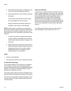
Table 3: Typical Divider Valve
Combinations
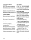
Divider Valves
A Series-Flo type divider valve is a manifold proportion-
ing device consisting of an inlet and end section plus a
minimum of three valve sections. The divider valve is
manifolded together with tie rods and nuts. A master
divider valve is the first divider valve downstream from
the lube pump. A secondary divider valve is any divider
valve receiving lubricant from the master divider valve.
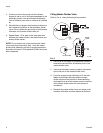
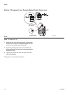
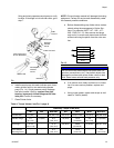
Valve Sections (MSP, MHH and MXP
modular-type, divider valves, only)
Valve sections (three or more required per manifold)
contain a piston specially fitted to that section, built in
outlet check valves and various passageways that,
working with the piston, meters and valves the flow of
lubricant (F
IG. 3).
Valve sections may be manufactured to require one or
two lube outlets. Stamping located on the face of each
section indicates:
• the style of divider valve section, i.e., MSP, MX,
etc.,
• the discharge per piston stroke expressed in
thousandths of cubic inches (35 = .035 in
3
)
and,
• the number of lube outlets required (S = single,
one outlet only; T = twin, two lube outlets
required).
FIG. 2
MASTER SECONDARY
TYPE OF
APPLICATION
MJ MD Machine tools, Printing,
Wire Forging &
Packaging Machinery
MSP MJ, MSP Machine tools, Textile,
Glass & Can Machinery,
Mobile Equipment
MX, MXP MX, MXP, MSP Cranes, Presses, Steel
Mills, etc.
MGO MX Levellers, Shears,
Conveyors, etc.
A
B
C
D
E
F
G
H
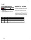
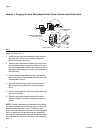
FIG. 3
TI11102
Piston
Enclosure/End
Enclosure Plug Gasket
Piston
Indicator
Indicator Port Plug
Port
O-Rings
Check
Valve
Plug