


Setup
6 312497P
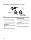
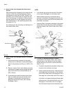
4. Continue to stroke the pump until the lubricant
purges all the air out of the internal passages of the
secondary divider valve and lubricant flows freely
from all indicator ports with no evidence of included
air.
5. Reinstall the port plugs or performance indicators in
their respective positions in the secondary divider
valve. Do not replace the port plugs or performance
indicators in the master divider valve yet.
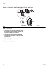
6. Repeat Steps 1-5 for each of the other lube lines
between the master divider valve and all other sec-
ondary divider valves.
NOTE: Do not replace any of the performance indica-
tors or port plugs removed in Step 1 from the master
divider valve assembly until the air-purging procedure
described in Section 3 (Filling Master Divider Valve) has
been completed.
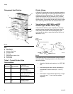
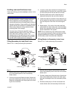
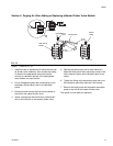
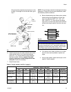
Filling Master Divider Valve
Refer to FIG. 6. when performing this procedure.
1. Verify that all port plugs or performance indicators
have been removed from all indicator ports in the
master divider valve.
2. Verify that the system pump is properly connected
to the inlet port of the master divider valve.
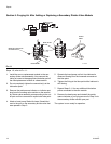
3. Cycle the system pump sufficiently to fill the main
feeder line between the pump and the master
divider valve and the lubricant is observed being
discharged from all of the indicator ports on the front
of the master divider valve with no evidence of
included air.
4. Reinstall the master divider valve port plugs or per-
formance indicators into their respective positions.
FIG. 6
TI11000
MASTER
BLEED
SECONDARY
LUBE POINT
HERE
CYCLE PUMP