


Installation
308778L 5
Installation
Dust and Foreign Matter
Avoid having dust or foreign matter enter the flow meter
by taking the following precautions:
• Thoroughly flush the fluid supply lines before install-
ing the flow meter.
• When installing fittings, make sure that no sealing
tape overlaps into the inside of the pipe.
• Install a 100 mesh fluid filter upstream of the flow
meter.
Installing the Flow Meter
• Flow volume can only be measured at the location
where the flow meter is installed.
• The Fluid Flow Meters are intrinsically safe for Class
I; Division 1; Group D hazardous indoor (NEMA 1)
locations when installed with an intrinsically safe
power device and wiring.
Refer to ANSI standards ISA-RP12.6, NEC Article
504 and the Canadian Electrical Code Appendix F.
• Do not use more than 200 ft. (61 m) of cable.
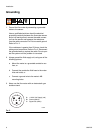
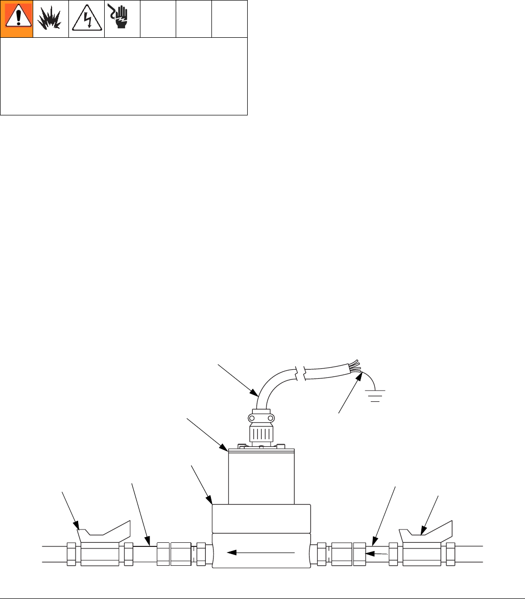
• Refer to F
IG. 1 to locate and install the flow meter,
connectors, and fluid shutoff valves. Install a check
valve to prevent backflow. The arrows on the flow
meter and check valve show the direction of fluid
flow.
• The shutoff valves allow you to isolate the meter for
service.
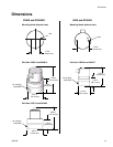
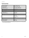
• Refer to the Technical Data and Dimensions
Drawings for dimension, inlet/outlet size, tempera-
ture and other specifications.
• All electrical equipment must only be installed by
a qualified electrician.
• Understand and follow your local code and safety
regulations for hazardous location wiring of intrin-
sically safe circuits.
FIG. 1: Typical Installation
7379A
Cable
Electronic Sensor Device
Flow Meter
Fluid LineFluid Shutoff Valve
on outlet side
Ground Sheath
Check Valve Fluid Shutoff Valve
on outlet side