


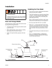
Installation
6 308778L
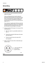
Grounding
1. Ground the flow meter by connecting a grounded
cable to the sensor.
Have a qualified electrician check the electrical
grounding continuity between the flow meter sensor
and a true earth ground; remove the cable connec-
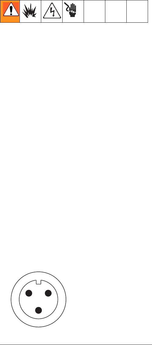
tor from the sensor and measure the resistance
from the cable connector Pin B to true earth ground.
Refer to F
IG. 2.
If the resistance is greater than 25 ohms, check the
cable ground connection. Refer to F
IG. 2. Reconnect
the ground sheath or replace the cable. Do not oper-
ate the system until the problem is corrected.
2. Always ground the fluid supply unit, using one of the
following options:
a. Mount the meter to a grounded conductive sur-
face, or
b. Connect the conductive fluid hose to the meter
inlet and outlet, or
c. Connect a ground wire to the meter's M6
mounting holes.
3. Never use the flow meter with an electrostatic gun
isolation stand.
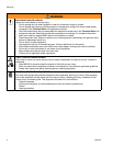
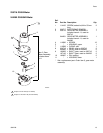
FIG. 2
7379A
A
B
C
A +10-30 Vdc Supply (red)
B Ground (black)
C Signal Out (white)