30
Transom Mount - Side Imaging®
5. Align the metal mounting bracket with the mounting holes. The center
slot should be above the two outer slots. (This bracket and all other
hardware supplied is top quality stainless steel for maximum strength
and corrosion protection.) Insert the three #10 - 1" long screws into the
drilled holes, but do not completely tighten.
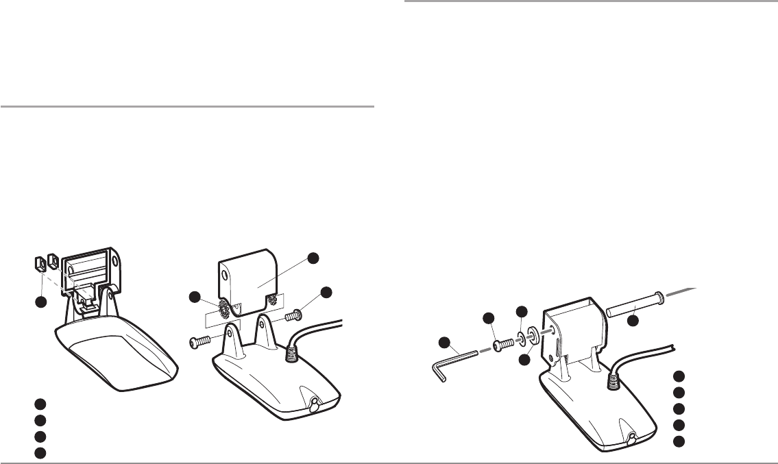
Attaching the pivot to the transducer
1. Attach the pivot to the transducer body, using the two 1/4"-20 x 5/8"
(16 mm) machine screws, toothed washers, and square nuts. The
toothed washers must fit on the inside of the transducer ears,
between the pivot and the ears. The square nuts will be prevented
from rotating by the pocket in the back of the pivot. An Allen wrench
is provided which fits all the 1/4"-20 screws, but do not fully tighten
the screws at this time.
Mounting the transducer pivot assembly to the bracket
1. Slide the assembled transducer into the metal bracket from the
bottom, aligning the large hole at the top of the bracket with the
hole in the pivot.
2. Insert the headed pin through the pivot holes in the bracket and
pivot. The headed pin can be inserted from either side of the
bracket.
3. Place the nylon washer over the opposite end of the headed pin.
Place the stainless washer over the 1/4"-20 x 5/8" (16 mm) screw
threads, then insert into the opposite end of the headed pin and
finger tighten only. The screw has a thread locking compound on the
threads to prevent loosening, and should not be fully tightened until
all adjustments are made.
NOTE: The running position of the transducer is now completely adjustable.
Subsequent adjustment may be necessary to tweak the installation after high
speed testing.
Attach the Pivot
2
3
4
1
Insert the square nuts
1
Toothed Washer
2
Pivot
3
Machine Screw
4
Screw
1
Headed Pin
2
Allen Wrench
3
Nylon Washer
4
Stainless Washer
5
3
1
5
4
2


