


4
2
PANEL DESCRIPTION
2
3
2
PANEL DESCRIPTION
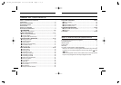
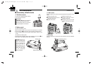
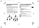
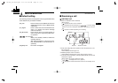
■ Front, top and side panels
NOTE: If the speaker netting (for dust proofing) becomes wet,
dry it with a hair drier (cool mode) etc. before operating the
transceiver. Otherwise the audio may be difficult to hear for
loss of the sound pressure.
q
w
e
r
t
y
i
u
Microphone
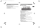
Function display
(p. 6)
Speaker
(See the following
NOTE.)
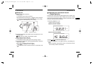
q VOLUME CONTROL [VOL]
Turns power ON and adjusts the audio level.
w RED BUTTON
The desired function can be assigned by your dealer.
e ANTENNA CONNECTOR
Connects the supplied antenna.
r SPEAKER-MICROPHONE CONNECTOR [SP MIC]
Connects the optional speaker-microphone. (p. 46)
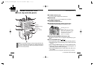
t DEALER-PROGRAMMABLE KEYS [P0] to [P3]
The desired functions can be assigned independently by your
dealer.
y CH UP AND DOWN KEYS [ ]/[ ]
➥ During standby condition, push to select an operating channel.
➥ After pushing [TX Code CH Select], push to select a TX code
channel.
➥ After pushing [DTMF Autodial], push to select a DTMF channel.
➥ After pushing and holding [Scan A Start/Stop]/[Scan B
Start/Stop], push to select a scan group.
➥ After pushing [Digital], push to select a BIIS code, status num-
ber or SDM.
*Desired functions can be assigned independently by your dealer.
☞ Continue to the next page.
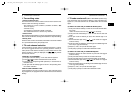
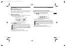
[SP MIC] jack cover
NOTE: KEEP the [SP MIC]
jack cover attached to the
transceiver when the speaker-
microphone is not used.
(See p. 2 for details)
!IC-F50_F60 BIIS.qxd 03.9.12 8:49 AM Page 3 (1,1)