


16
4
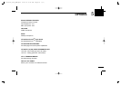
CONNECTION AND MAINTENANCE
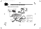
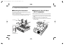
■ Optional UT-109 or UT-110
installation
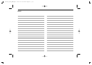
q Turn the power OFF, then disconnect the DC power cable.
w Unscrew the 4 cover screws, then remove the bottom
cover.
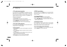
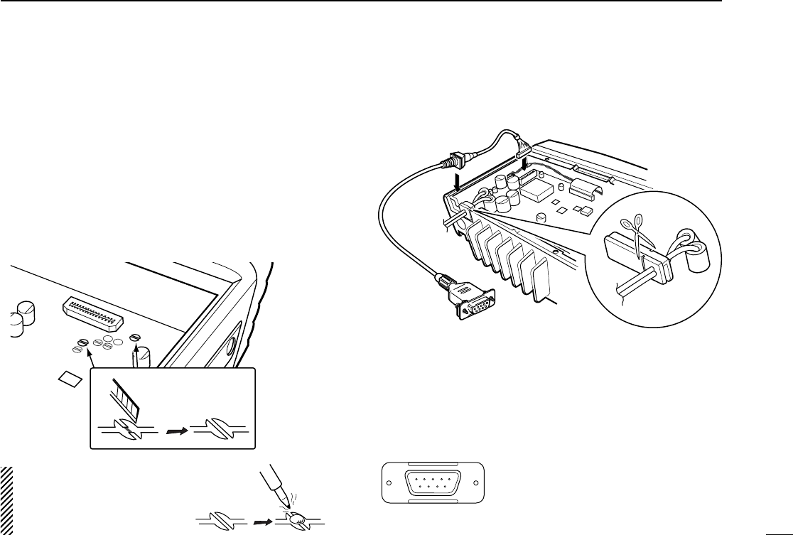
e Cut the pattern on the PCB at the TX mic circuit (MIC) and
RX AF circuit (DISC) as shown below.
r Install the scrambler unit as described in the installation of
optional UT-105, UT-108 or UT-111 as on the page at left.
t Replace the bottom cover and screws.
NOTE: Be sure to re-solder the
above disconnected points
when you remove the scrambler
units. Otherwise no TX modula-
tion or AF output is available.
MIC
DISC
Front panel
q
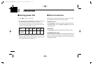
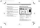
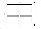
Dimmer cont. IN or
IGSW cont. IN
w AF OUT
e Det. AF OUT
r Mod. IN
t PTT control IN or
y Horn drive cont. OUT
u AF GND
i Det. AF GND
o Mod. GND
OPTIONAL CABLE PIN ASSIGNMENT
t r e w q
o i u y
FTSW control IN
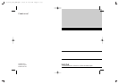
OPC-617
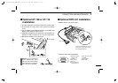
Cut off the bushing as in the
illustration, when you install
the optional OPC-617.
■ Optional OPC-617 installation
Install the OPC-617 as shown below.
IC-F110_F210_GEN.qxd 02.12.11 4:25 PM Page 16 (1,1)