


AIR SUPPLY REQUIREMENTS
ARO Cylinders are pneumatic devices which convert compressed air
into linear motion. Cylinders are widely used for such things as: clampĆ
ing, pushing or pulling motion, product assembly, stamping and tensionĆ
ing. The product offering ranges from light to heavy duty industrial apĆ
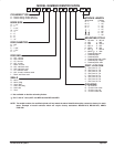
plications operating on air pressures up to 250 p.s.i.g. (17.2 bar). Model
options include:
Stainless steel rod for corrosive environments, low friction packings and
cushion versions used to decelerate heavy loads. For detailed information
on models offered refer to the ARO Cylinder catalog.
WARNINGS AND PRECAUTIONS
WARNING
Do not exceed maxiĆ
mum working pressure which can result in serious injury or property
damage. Use an air regulator to limit pressure to the cylinder.
WARNING
DeĆpressurize the system before cleaning, inspection, reĆlubrication,
servicing or disassembly to prevent injury from accidental cycling.
WARNING
Keep clear of moving cylinders
and fixtures to avoid injury.
AIR AND LUBE REQUIREMENTS
Proper moisture removal and filtration of contaminates will promote
good service life and operation.
Install an air regulator to control the operating pressure, insure smooth
operation and conserve energy.
ARO pneumatic cylinders are lubricated at the factory. This lubrication
should provide satisfactory operation and cycle life. The use of lubriĆ
cated air will however help to extend the cycle life.
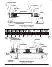
INSTALLATION
Cylinders must only be installed by a competent technician who underĆ
stands the system requirements, mechanical principles and equipment
involved. NOTE: Improper alignment of the cylinder can cause excesĆ
sive wear on the rod seals. Check rod alignment to the machine parts
in both the retracted and extended positions.
S Install the air regulator as close as practical to the cylinder.
S Keep cylinder ports plugged or covered prior to assembly to prevent
contamination which can contribute to premature failure.
S Use Teflon tape on the air fittings to prevent leakage.
OPERATION
Improper application, installation, service or maintenance of ARO CylinĆ
ders can cause bodily injury or shortened product life. Contact the ARO
Corporation for questions concerning special applications.
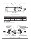
This feature can increase cylinder life. However, it should not be used
exclusively to decelerate heavy loads. Cushioned cylinder models are
equipped with adjustable needle valves in the end cap(s) for easy, preĆ
cise adjustment of the cushion effect.
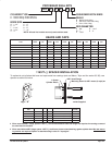
The cushion seal is a floating" O" ring which seals
on a cushion boss, a part of the piston assembly. As the cushion boss enĆ
ters the cushion O" ring located in the head or cap, the main air exhaust
flow is blocked and forced through a bypass passage containing the
needle valve. The cushion effect is created by the resulting back pressure.
The cushion needle is used to vary the restriction (back pressure) and
control the degree of cushioning. Upon application of the air in the oppoĆ
site direction, the incoming air forces the O" ring cushion seal towards the
inside of the cylinder and acts as a check valve in the free flow direction.
Incoming air flows around the o.d. of the seal providing full flow to the pisĆ
ton face with little or no pressure drop for quick stroke reversal.
S Turn cushion effect.
S Turn cushion effect.
DO NOT ROTATE CUSHION ADJUSTMENT
NEEDLE COMPLETELY CLOCKWISE; Complete shutoff of the cushĆ
ion adjustment needle valve will prevent the cylinder from completely exĆ
tending or retracting.
MAINTENANCE
Periodic cylinder maintenance should be performed to insure maximum
service life.
S Clean the air filter / regulator bowl regularly. Relieve system pressure,
empty the contents of the bowl and clean or replace the filter element.
S Check the fluid level in the lubricator regularly, replenish with the apĆ
propriate air line lubricant.
S Filtered air should be used to operate cylinders. Dirty air will damage
seals and reciprocating parts.
S Metallic parts should be cleaned with a nonĆflammable solvent.
S Rubber parts should be cleaned with soap and water.
S Cleaned parts should be rinsed and dried using low pressure air.
S Replace any parts which are worn or damaged. Selected parts and
seals are available in repair kit form.
S Lubricate moving parts and seals.
S Do not attempt to disassemble pistons from rods. High heat is reĆ
quired and piston and / or piston rod damage will result.
Do not attempt to grip the piston rod with pliers or wrenches
which can cause scouring. Nicks or scratches on the piston rod will damĆ
age the rod seals.
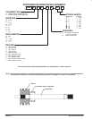
ASSEMBLY
Verify that all seals are in the correct position and that the rod and piston
seals have been properly lubricated with Accrolube or agnalube grease.
Torque Specifications:
Cap Screws Female Bolts
1Ć1/2" 9 ft lbs (12.2 Nm) 6 ft lbs (8.1 Nm)
2" 16 ft lbs (21.7 Nm) 10 ft lbs (13.6 Nm)
2Ć1/2" 21 ft lbs (28.5 Nm) 10 ft lbs (13.6 Nm)
3Ć1/4" 35 ft lbs (47.5 Nm) 20 ft lbs (27.1 Nm)
4" 49 ft lbs (66.4 Nm) 20 ft lbs (27.1 Nm)
5" 45 ft lbs (61 Nm) N/A
6" 55 ft lbs (74.6 Nm) N/A
8" 110 ft lbs (149.2 Nm) N/A
10" 125 ft lbs (169.5 Nm) N/A
The assembled cylinder can now be tested for leaks and proper operation.
1. Alternately apply 90 p.s.i.g. (6.2 bar) air pressure to each of the cylinĆ
der ports and test for internal leaks across the piston and external
leaks at the barrel seals and the rod seal.
2. Test for proper cycling at 20 p.s.i.g. (1.4 bar) supply.