


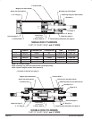
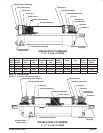
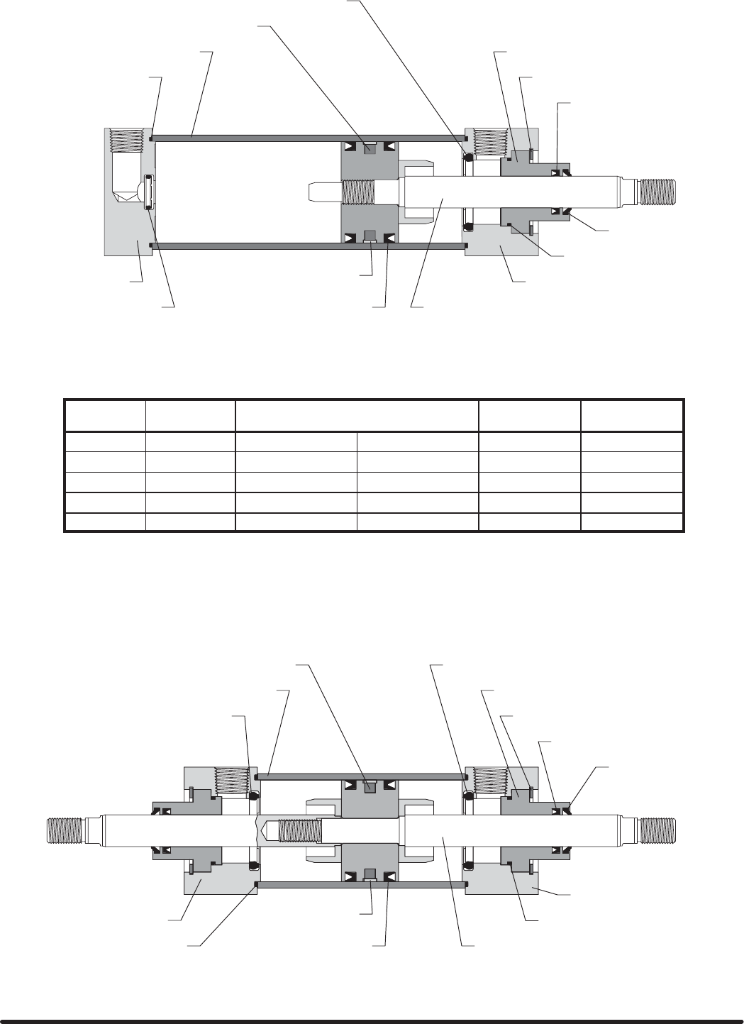
Q Cushion Seal
Retaining Ring (see table below)
Barrel (see table below)
Q “O” Ring (2)
Cap (see page 7)
“O” Ring Q
Q Cushion Seal
Bushing (see table below)
Rod Seal Q
Wiper Q
Head (see page 7)
Reciprocating Assembly (see page 6)
Q “O” Ring (2)
Retaining Ring (2) (see table above)
Barrel (see table above)
Head (see page 7)
Bushing (2) (see table above)
Rod Seal (2) Q
Wiper (2) Q
Head (see page 7)
Reciprocating Assembly (see page 6)
Q Cushion Seal
SINGLE ROD CYLINDERS
1-1/2”, 2”, 2-1/2”, 3-1/4” and 4” BORE
DOUBLE ROD CYLINDERS
1-1/2”, 2”, 2-1/2”, 3-1/4” and 4” BORE
Q Included in Seal Kit (see page 7).
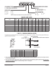
Magnet (see table below)
Q Wear Strip
(must be used)
Q Piston Seal (2)
“O” Ring (2) Q
Magnet (see table above)
Cushion Seal Q
Q Wear Strip
(must be used)
Q Piston Seal (2)
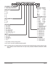
BORE SIZE BARREL
NUMBER
BUSHING NUMBER
STANDARD ROD OVERSIZE ROD
RETAINING
RING
MAGNET
(OPTIONAL)
1-1/2” 119572-X 119454 N/A 119549-125 119681-150
2” 119573-X 119455 119456 119549-162 119681-200
2-1/2” 119574-X 119455 119456 119549-162 119681-250
3-1/4” 119575-X 119457 119458 119549-212 119681-325
4” 119576-X 119457 119458 119549-212 119681-400
NOTE: “X” = Stroke Length.
NOTE: Retaining ring must be replaced when replacing bushing.
NOTE: Optional magnet resides under wearstrip.