


559X
Page2of4
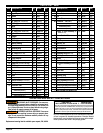
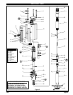
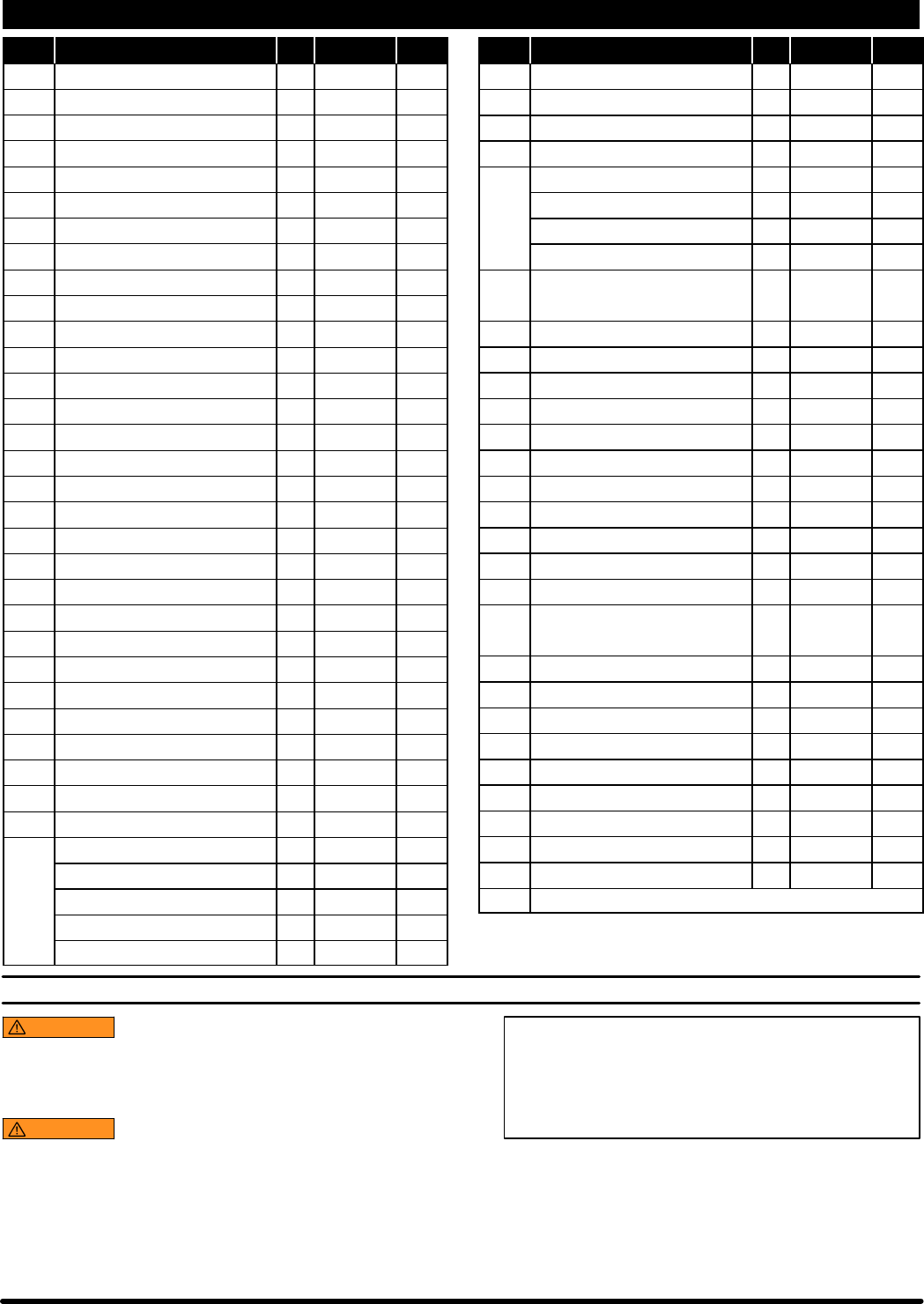
PARTS LIST / 559X
Item Description (size) Qty Part No. [Mtl] Item Description (size) Qty Part No. [Mtl]
1 Carriage Bolt (1/4” - 20 x 9” long) (4) 94333 [C]
2 Upper Cap (1) 94307 [Z]
n 3 Gasket (2) 94311 [B]
4 Sleeve (2) 94316 [Br]
n 5 “O” Ring (1/16” x 11/16” o.d.) (4) Y325-15 [B]
n 6 “O” Ring (1/8” x 3/4” o.d.) (4) Y325-206 [B]
7 Spool (2) 94310 [D]
n 8 “U” Cup (1/8” x 3/4” o.d.) (2) Y240-7 [B]
n 9 “O” Ring (0.106” x 0.587” o.d.) (2) 15066-PM [B]
10 Cylinder (1) 94249 [A]
11 Adapter (1) 94447 [C]
n 12 “O” Ring (1/16” x 3/4” o.d.) (1) Y325-16 [B]
n 13 “O” Ring (1/16” x 7/16” o.d.) (1) Y325-11 [B]
14 Muffler Housing (1) 95086 [C]
15 Foam Liner (2) 94402
16 Retaining Ring (1) 94406 [C]
17 Washer (1) 94515 [C]
n 18 “U” Cup (3/16” x 2” o .d.) (2) Y240-23 [B]
19 Piston (1) 94780 [D]
20 Piston Adapter (1) 94388 [C]
n 21 “O” Ring (3/32” x 1” o.d.) (1) Y325-117 [B]
22 Dowel Pin (1/4” o.d. x 7/8” long) (1) Y148-37 [C]
n 23 “O” Ring (3/32” x 13/16” o.d.) (1) Y325-114 [B]
n 24 Rod Seal (1) 95139 [U]
25 Washer (1) 94785 [C]
26 Spring (1) 94705 [C]
27 Base (1) 67241 [C/Z]
28 Nut (1/4” - 20) (4) 93828 [SS]
29 Ground Screw (#10 - 32 x 1/4”) (1) 93005 [C]
n 30 Gasket (1) 70834 [Co]
31 Extension Tube
models 5596 (7.531’’) (1) 94401-2 [C]
models 5597 (10.281’’) (1) 94401-6 [C]
models 5598 (18.219’’) (1) 94401-3 [C]
models 5599 (27.781’’) (1) 94401-4 [C]
n 32 Gasket (1) 70837 [Co]
33 Piston Rod (1) 95137 [C]
34 Pin (1) 94786 [C]
n 35 Cotter Pin (1/16” x 1/2” long) (1) Y15-21 [C]
36 Connector - 5596 (3.457”) (1) 94340-2 [C]
models 5597 (6.207”) (1) 94340-6 [C]
models 5598 (14.145”) (1) 94340-3 [C]
models 5599 (23.707”) (1) 94340-4 [C]
Piston & Tube Assembly (in-
cludes 37 - 41)
(1) 67262
37 Lower Suction Tube (1) [C]
38 Plunger (1) [C]
39 Ball Stop (1) 83276 [C]
40 Ball (9/32” dia.) (1) Y16-209 [C]
41 Primer Rod (1) 95134 [C]
n 42 Guide Washer (1) 95131 [Co]
43 Spacer (1) 72392-1 [C]
n 44 Retaining Ring (0.877” o.d.) (1) 76243-1 [C]
n 45 “U” Cup (1/8” x 13/16” o.d.) (1) Y186-54 [B]
n 46 Guide (1) 95132 [T]
47 Foot Valve Body (1) 95133 [SH]
FootValveAssembly(includes44
- 47)
(1) 67242
n 48 Gasket (1) F21-65 [Co]
49 Valve Seat (1) 6797 [C]
50 Primer (1) 94400 [C]
n 51 Retainer Ring (1) 94397 [C]
52 Primer Tube (1) 94399 [C]
K 53 Bung Assembly (includes 54) (1) 67145-2 [ZA]
K 54 Thumb Screw (1/4”-20x1”) (3) Y66-59-C [C]
n Gadus S2 U1000 Grease Packet (1) 94833
n Parts in Repair Kit 637385
K Not included with models 5597
OPERATING AND SAFETY PRECAUTIONS
WARNING
EXCESSIVE INLET PRESSURE. Can cause ex-
plosion resulting insevere injuryor death.Donot exceedmaxi-
mum operating pressure of 517 bar(7500 p.s.i.) at 10.3 bar (150
p.s.i.) inlet air pressure. Donotrun pump without using a regu-
lator to limit air supply pressure to the pump.
WARNING
EXCESSIVE MATERIAL PRESSURE. Can cause
equipment f ailure resulting in severe injury or property dam-
age. Do not exceed the maximum material pressure of any
component in the system.
Replacement warning label is available upon request, PN \ 94520.
PUMP RATIO X
INLET PRESSURE TO PUMP MOTOR
=
MAXIMUM PUMP
FLUID PRESSURE
Pump ratio isan expression ofthe relationship between the pumpmotor areaand
the lower pump end area. EXAMPLE: When 10.3 bar (150 p.s.i.) inlet pressure is
supplied to the motor of a 50:1 ratio pump it will develop a maximum of 517 bar
(7500 p.s.i.)fluid pressure (at noflow) -- asthe fluid controlis opened,the flow rate
will increase as the motor cycle rate increases to keep up with the demand.
NOTICE: Thermal expansioncan occur whenthefluid in the materi-
al lines is exposed to elevated temperatures. Example: Material
lines located in a non-insulated roof area can warm due to sunlight.
Install a pressure relief valve in the pumping system.