


559X
Page4of4
PUMP DISASSEMBLY
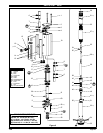
NOTE: Allthreads are righthand. Referto figure2 (page 3). Discon-
nect air supply and relieve all system pressure
prior to servicing.
Carefully removethe parts, inspect for damage,nicks or excessivewear
and determine if any parts will need replacement.
1. Using a 7/8” wrench, unthread and remove (11) adapter, containing (12
and 13) “O” rings, releasing (14) muffler housing.
2. Using a 7/16” wrench, remove (28) nuts.
3. Remove four (1) bolts, (2) upper cap and (3) gasket.
4. Remove (10) cylinder, containing (4) sleeves and (7) spools.
5. Using (1) bolt, push (7) spools and (4) sleeves out “sleeve” end of
(10) cylinder.
6. Remove (16) retaining ring, (17) washer and (19) piston.
7. Remove (22) dowel pin, releasing (20) piston adapter.
8. Remove (3) gasket.
9. Clamp (31) extension tube horizontally in a vise. Unthread and re-
move (27) base, (30) gasket, (26) spring and (25) washer. NOTE:
Remove (24) rod seal only if replacement is necessary.
10. Pull up on (33) piston rod to reveal (35) cotter pin.
11. Remove (35) cotter pin and (34) connecting pin, releasing (33) pis-
ton rod.
12. Using (33) piston rod, push down on (36) connector until it bottoms.
13. Remove (51) retainer ring.
14. Push (50) primer up into (52) primer tube.
15. Lightlywedgea flat blade screwdriver between (50) primer and (52)
primer tube, so (50) primer unthreads with (52) primer tube.
16. Insert a 5/16” diameter rod thru the cross holes in (52) primer tube
and use the rod to unthread and remove (52) primer tube.
17. Remove(43) spacer, (48) gasketand(49) valveseat from(52)prim-
er tube.
18. Remove (44 - 47) foot valve assembly from (41) primer rod.
19. Remove (44) retaining ring, releasing (45) “U” cup. NOTE: Do not
remove (46) guide unless replacement is necessary.
20. Remove (42) guide washer.
21. Clamp (37) lower suction tube horizontally in a vise. Unthread and
remove (31) extension tube and (32) gasket.
22. Using a 7/32” diameter rod in the cross hole in (36) connector and a
9/16” wrench on the flats of (38) plunger, unthread and remove (36)
connector from (38) plunger. NOTE: Do not damage the o.d. of (38)
plunger in any way.
23. Using a 5/32” diameter rod in the cross hole of (41) primer rod and a
9/16” wrench on flats of (38) plunger, unthread and remove (41)
primer rod, releasing (40) ball and (39) ball stop.
PUMP REASSEMBLY
NOTE: Thoroughly clean and lubricate all seals and bores with
Shell Gadus S2 U1000 upon assembly. Replace all soft parts with
new ones included in the repair kit. Note: Refer to the illustration (fig-
ure 2, page 3) for “U” cup lip seal direction.
1. Assemble (39)ballstop and (40)ball into (38) plunger, securing with
(41) primer rod. NOTE: Torque (41) primer rod to 7.9 - 11.3 Nm (70 -
100 in. lbs).
2. Thread (36) connector to (38) plunger, using a 7/32” diameter rod
thru thecross holeto tighten.NOTE: Tighten (36)connector to23.0 -
33.9 Nm (17 - 25 ft lbs).
3. Assemble (46) guide and (45)“U”cup into (47) valve body, securing
with (44) retaining ring. NOTE: Assemble chamfered corner of (46)
guide into (47) valve body first.
4. Assemble (42) guide washer and (44 - 47) foot valve assembly onto
(41) primer rod.
5. Assemble (43) spacer, (48) gasket and (49) valve seat onto (41)
primer rod.
6. Thread (50) primer onto (41) primer rod, securing with (51) retainer
ring.
7. Thread (52) primer tube to (37) lower suction tube and tighten.
NOTE: Torque (52) primer tube to 88.1 - 101.7 Nm (65 - 75 ft lbs).
8. Assemble (33) piston rod to (36) connector, securing with (34) con-
necting pin and (35) cotter pin.
9. Assemble (32) gasket and (31) extension tube to (37) lower suction
tube and tighten. NOTE: Torque (31) extension tube to 88.1 - 101.7
Nm (65 - 75 ft lbs).
10. Assemble (23) “O” ring, (24) rod seal, (25) washer, (26) spring and
(30) gasket into(27) base and assemble(27) base to (31) extension
tube. Clamp (27) base horizontally in a vise and tighten (31) exten-
sion tube. NOTE: Torque (31) extensiontubeto88.1 - 101.7 Nm (65
-75ftlbs).
11. Push up on (50) primer, exposing (33) piston rod.
12. Assemble (3) gasket to (27) base.
13. Assemble(21) “O”ring to (20)pistonadapterandassemble (20)pis-
ton adapter to (33) piston rod, securing with (22) dowel pin.
14. Replace (18) “U” cups on (19) piston and assemble(19) piston onto
(20) piston adapter, securing with (17) washer and (16) retaining
ring.
15. Replace (5) “O” rings on (4) sleeves and assemble (4) sleeves into
(10) cylinder. NOTE: Assemble eachsleeve into the end ofthe cylin-
der nearest the exhaust hole.
16. Replace (6 and 9) “O” rings and (8) “U” cups on (7) spools and as-
semble (7) spools into (10) cylinder from the opposite end as the (4)
sleeve went in.
17. Assemble (10) cylinder onto the pump, being careful when sliding
over the lips of (18) “U” cups. NOTE: Be sure (3) gasket is seated
properly.
18. Replace (3) gasket on (2) upper cap and assemble (2) upper cap to
(10) cylinder.
19. Assemble (1) bolts to pump, securing with (28) nuts. NOTE: Torque
(28) nuts to 9.0 - 10.2 Nm (80 - 90 in. lbs).
20. Replace (12 and 13) “O” rings on (11) adapter.
21. Assemble (15) foam liners to (14) muffler housing.
22. Assemble (14) muffler housing to (10) cylinder, securing with (11)
adapter. NOTE: Torque (11) adapter to 7.9 -9.0 Nm (70 -80 in. lbs).
TROUBLE SHOOTING
If the pump will not cycle or will not deliver material.
• Becertain tocheck fornon-pump problemsincluding kinked,restric-
tive orplugged inlet/outlet hoseor dispensingdevice.Depressurize
the pump system and clean out any obstructions in the inlet / outlet
material lines.
• Check all seals, including track gaskets.
• Check direction of “U” cup lips.
PN 97999-1033