


Page2of4 612041-X
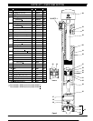
PARTS LIST / AIR MOTOR SECTION
Item Description (size in inches) Qty Part No. [Mtl]
1 Cap (1) 76073-2 [A]
2 Washer (1) 77290 [C]
n 3 “O” Ring (3/32” x 2-5/16” o.d.) (1) Y325-138 [B]
4 Spring (1) 77208 [C]
5 Button (1) 90638 [C]
6 Cylinder (1) 76074-2 [A]
n 7 Spacer and Piston Assembly (1) 61088
8 Screw (#4-40x3/8”) (3) Y222- 54-C [C]
9 Valve Plate (1) 76090 [C]
10 Piston Assembly (1) 60656 [B/C]
11 Valve Spacer (1) 76856 [D]
n 12 Gasket (1) F21-53
[Co]
13 Plunger Tip (1) 77794 [C]
n 14 “O” Ring (1/8” x 1-1/4” o.d.) (1) Y325-214 [B]
15 Plunger (1) 76215 [C]
n 16 “O” Ring (3/32” x 2-1/16” o.d.) (1) Y325- 134 [B]
17 Spring (1) 76070 [C]
18 Pump Body (1) 77807 [A]
n 19 “O” Ring (.275” x 1.837” o.d.) (1) 77803 [B]
20 Ground Screw (#10 - 32 x 1/4”)(page 3) (1) 93005 [C]
21 Dowel Pin (3/16” dia. x 1-1/8”) (1) Y148-29 [C]
n Parts in Repair Kit 637084
MATERIAL CODE
[A] = Aluminum [CI] = Cast Iron [SS] = Stainless Steel
[B] = Nitrile [Co] = Copper [T] = PTFE
[Br] = Brass [D] = Acetal [V] = Viton
[C] = Carbon Steel [NY] = Nylon
1
3
2
4
5
6
8
9
10
11
7
12
13
14
15
17
16
18
19
21
Figure 2
1/4 N.P.T.F. - 1
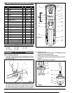
PUMP DISASSEMBLY
NOTE: All threads are right hand.
1. Place the 2” differential pump in a vise. Rotate the pump so the ma-
terial outlet is resting against the vise jaw. CAUTION: Do not clamp
the pump too tightly.
Figure 3
2. Place a strap wrench around the (1) cap and remove the cap. If the
(6) cylinder comes off with the (1) cap, place the cap in a vise and
use a strap wrench around the (6) cylinder to unscrew it from the
cap. NOTE: Do not squeeze or use a pipe wrench on (6) cylinder.
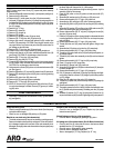
3. Remove (3) “O” ring.
4. Usinga strapwrench, asshownin figure3, unthreadandremove the
(6) cylinder from the (18) pump body.
5. Remove (16) “O” ring from the (18) pump body.
6. Unthread and remove (7) spacer and piston assembly from the (13)
plunger tip.
7. Remove (12) gasket from (13) plunger tip.
9
Figure 4
10
11
8
35
37
38
22
39
(continued on page 4)