


PN 97999-93
Page4of4 612041-X
PUMP DISASSEMBLY (continued)
NOTE: Perform steps 8 thru 10 only if (7) spacer and piston assembly
needs servicing.
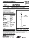
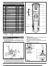
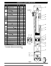
8. Remove the three(8) screws fromthe(11) valvespacer (see figure4).
9. Remove the (9) valve plate.
10. Remove the (11) valve spacer from the (10) piston assembly.
11. Unthread (13)plunger tipfrom the(15)plunger byusingawrenchon
the flats of the (13) plunger tip and a strap wrench on the (15) plung-
er. CAUTION:Place the strap wrench onthevery upper mostpartof
the (15) plunger.
12. Remove (14) “O” ring.
13. Remove (21) dowel pin.
14. Remove (13) plunger tip.
15. Remove (15) plunger.
16. Remove (17) spring from the (18) pump body.
17. Remove (19) “O” ring from the (18) pump body.
18. Using a pipe wrench, unthread and remove the (34) suction tube
from the (18) pump body. CAUTION: Place the pipe wrench on the
very upper most or very lower most part of the (34) suction tube. Do
not damage or dent this tube.
19. Remove (25) “O” ring from the (18) pump body.
20. Grasp the (22) piston rod and remove by pulling straight out.
21. Using a strap wrench on (36) tube, unthread and remove from (18)
pump body. CAUTION: Do not damage or dent this tube.
22. Remove (26) “O” ring from (18) pump body.
23. Remove (24) plug and (23) “O” ring.
24. Clamp the(43) intakevalve assembly ina vise. Usinga strapwrench
on (34) suction tube, unthread and remove from valve assembly.
CAUTION: Do not damage or dent this tube.
25. Using a wrench on flatsof (22)piston rod, unthreadand remove (39)
nut (see figure 4).
26. Remove (38) washer,(37) cup and(35) washerfrom (22) pistonrod.
27. Remove (32) retaining ring from the (22) piston rod, using retaining
ring pliers.
28. Remove (33) piston from (22) piston rod.
29. Remove two (30) packings (where applicable).
30. Remove (31) “O” ring from (22) piston rod.
31. NOTE: Do not remove (27) groove pin and (28) collar from (22) pis-
ton rod unless damage is evident. Remove (27) groove pin, releas-
ing (28) collar.
PUMP REASSEMBLY
1. Insert the(11) valve spacerthruthe bottomof the(10)piston assem-
bly (see figure 4).
2. Place the (9) valve plate on top of the (10) piston assembly, aligning
the three holes with the posts of (11) valve spacer.
3. Fasten the (9) valve plate down using the three (8) screws. Lay this
assembly aside for the moment.
4. Place the (28) collar on the (22) piston rod and secure with (27)
groove pin.
5. Assemble (29) washer next to (28) collar on (22) piston rod.
6. Grease and assemble (31) “O” ring to (22) piston rod.
7. Assemble two (30) packings to (33) piston (where applicable).
8. Assemble (33) piston to (22) piston rod, securing with (32) retaining
ring.
9. Assemble (35) washer, (37) cup (lips up) and (38) washer onto (22)
piston rod, securing with (39) nut (see figure 4).
10. Grease and assemble (23) “O” ring into (24) plug and screw (24)
plug into (18) pump body.
11. Place the (18)pumpbody in avise and rotateit so the material outlet
is resting against the vise jaw. CAUTION: Do not clamp the pump
body too tightly.
12. Grease and assemble (26) “O” ring to (18) pump body.
13. Thread (36) tube onto (18) pump body and tighten, using a strap
wrench.
14. Assemble the (22) piston rod up thru the (18) pump body.
15. Grease and assemble (25) “O” ring to (18) pump body.
16. Thread the (34) suction tube to the (18) pump body and tighten, us-
ing a strap wrench.
17. Thread the (43) intake valve assembly to the (34) suction tube and
tighten.
18. Grease and assemble (19) “O” ring into (18) pump body.
19. Place (17) spring into (18) pump body.
20. Assemble (15) plunger over (22) piston rod.
21. Assemble (13)plungertip to (22)piston rodand insert(21) dowelpin
to secure plunger tip.
22. Grease and assemble (14) “O” ring to (13) plunger tip.
23. Pull (15) plunger up and thread (13) plunger tip to plunger and tight-
en by using a wrench on flats of (13) plunger tip and a strap wrench
on (15) plunger.
24. Place the (12) gasket over the end of (13) plunger tip.
25. Thread the (7) spacer and piston assembly onto the (13) plunger tip
and tighten.
26. Grease and assemble (16) “O” ring to (18) pump body.
27. Thoroughly grease the inside of the (6) cylinder and assemble over
the (7) spacer and piston assembly, threading onto the (18) pump
body.
28. Assemble (2) washer, (3) “O” ring, (4) spring and (5) button into (1)
cap and assemblecapto (6) cylinder, tightening usinga strap wrench.
TROUBLE SHOOTING
Pump continually cycles.
• Checkfor empty material supply. Disconnect the air(fromthe pump)
replenish material supply.
• Check for worn or damaged (30) packing or (33) piston.
Material on one stroke only (fast downstroke).
• The intake valve assembly may not be checking or sealingproperly.
Remove the intake valve assembly and inspect. If the valve assem-
bly is damaged, replace with new parts. If the valve assembly is not
damaged, thoroughlyclean andreassembleto thepump (see pump
instructions).
Material on one stroke only (fast upstroke).
• Check for worn or damaged (37) cup. Replace cup (see pump
instructions and figure 4).
Material leakage out the top of the pump body.
• Check for worn or damaged (30) packing or (33) piston.
Air leakage out of the exhaust holes. (See Air Motor Instructions)
• Check to see if the (9) valve plate is loose or has become disas-
sembled from the (11) valve spacer.
• Check for worn or damaged (10) piston assembly.
• Check for worn or warped (9) valve plate.
• Worn or damaged (14) “O” ring. Replace (14) “O’’ ring.