


PAGE2OF4 650295
INSTALLATION
The 650295 Chop-Check Dispensing System comes completely asĆ
sembled. Remove unit from crate and place on a level surface. Install
material hose and dispensing device as required.
When the following instructions are observed, heavy paste materials
can be pumped directly from their original 5 or 55 gallon drum without
air inclusion, or excessive waste.The follower plate creates anair tight
sealas well as clean-wipingaction in itsprogressive downward moveĆ
ment into the drum.
OPERATING INSTRUCTIONS
OPERATING INSTRUCTIONS / INITIAL SETUP PROCEDURE
WARNING STAND CLEAR. When raising or lowering the
lift. Read the warning on page 2 of 651616-X Two Post Lift/Ram
Operator's Manual.
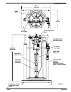
FOLLOWER PLATE
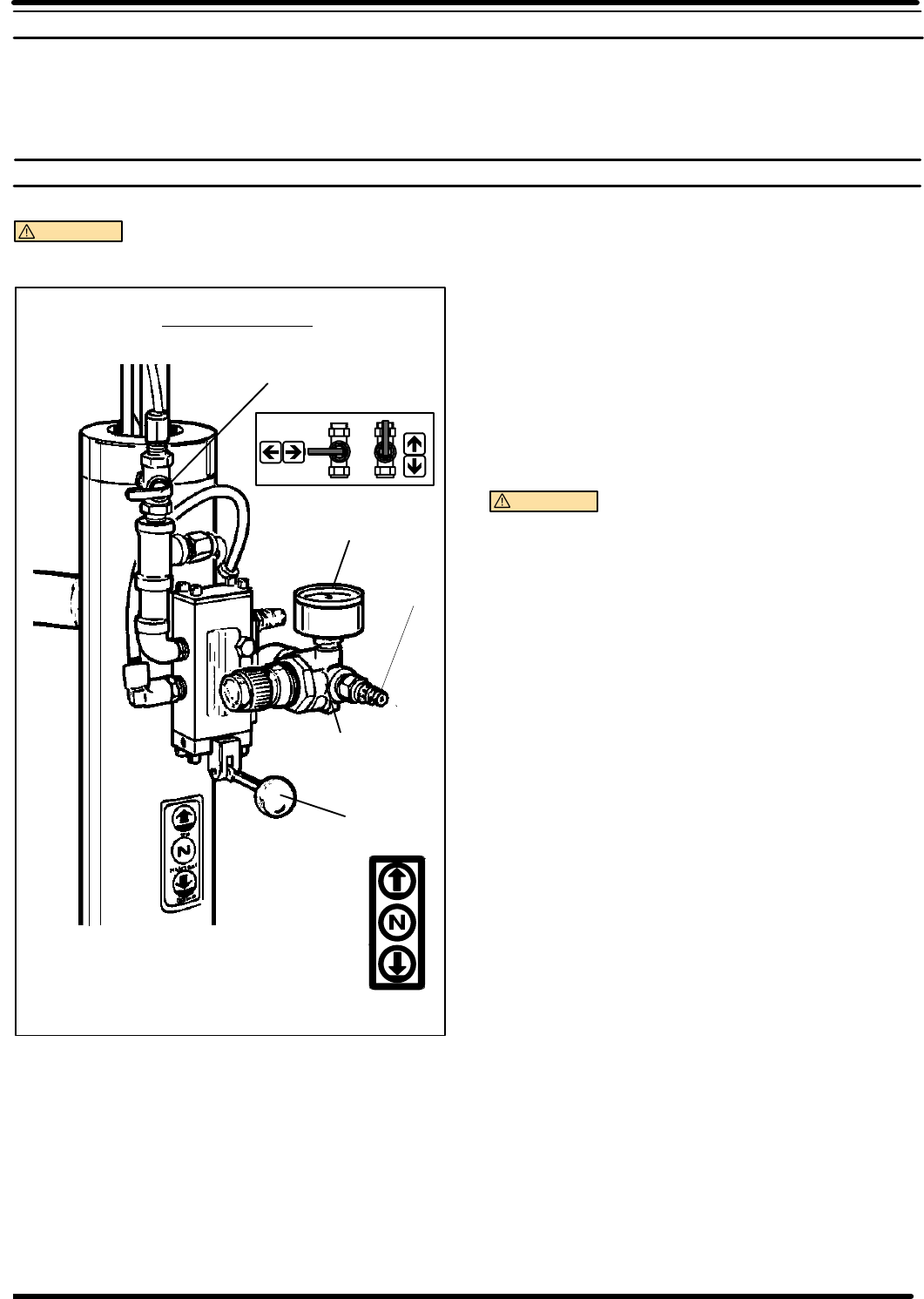
AIR SUPPLY VALVE
AIR CONTROLS
FIGURE 2
2
AIR
INLET
CONTROL
LEVER
GAUGE
OFF
ON
PRESSURE
REGULATOR
F034
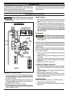
TO RAISE LIFT, (THE FIRST TIME):
1. Take note of the pump/drum clearance above. Be certain the lift is
clear of any objects above. Also refer to OPERATING AND SAFEĆ
TY PRECAUTIONS found on page 2 of 651616-X Two Post Lift/
Ram Operator's Manual.
2. Connect the air supply (160 PSI MAX) to the air inlet. Adjust (Turn Lift/
Ram Pressure Regulator Knob Clockwise) air pressure on lift/ram presĆ
sure regulator to 20 P.S.I. (1.2 Bar)
3. Shift the control valve lever to the ``UP'' position.
4. Raise the Lift/Ram high enough to clear the height of the drum.
Stop the lift upward travel by moving the control valve lever to the
(center) ``NEUTRAL'' position.
REFER TO PAGE 3:
1. Once Lift/Ram assembly and pumpare in the ``UP" position,place
andcenteranopened5or55 gallondrumof materialon thelift/ram
base.
2. Lubricatelowerfollower wiperplate seal withany typegrease. (siliĆ
cone, vaseline, gear, etc.) This ensures a smooth fit into the drum
as well as prevents curing type compounds from bonding to seal.
3. Checkvent plugon followerplate to besure iteasily threads inand
out. It is recommended to lubricate the threads of the plug to help
prevent possible set up of compound at this point. See 651616-X
Operator's Manual.
TO LOWER LIFT:
WARNING
PINCH HAZARD. Follower can descend quickly
causing injury. Keep hands clear when aligning with containĆ
er. Read the warning on page 2 of 651616-X Two Post Lift/Ram
Operator's Manual.
NOTE: Be certain the Follower Plate vent plug has been removed
sothat the air trapped between thefollower and the material isallowed
to escape from this vent. Captured air between the follower plate and
drum will escape.
NOTE: The Lift/Ram may hesitate momentarily before starting downĆ
ward, the air pressure inside the post air chamber must decrease beĆ
fore it will begin to descend.
1. Shift the control valve lever to the ``DOWN'' position and proceed
to lower the pump.
2. Replace the vent plug once the material begins to ooze from the
vent opening.
3. The unit is now ready for operation. Adjust (Turn pump regulator
Clockwise) air pressure on pump Filter/Regulator until pump beĆ
gins to cycle.
4. Trigger gun to prime pump with material.
TO RAISE LIFT, (NORMAL OPERATION):
1. Adjust the Follower Plate Air Valve pressure upto approximately 8
psig. DO NOT OVERPRESSURIZE THE DRUM to avoid damĆ
age.
NOTE: Air from this valve will only pass when the Control Lever is
in the ``UP'' position.
2. Shift the control valve lever to the ``UP'' position.
3. Raise the Lift/Ram high enough to clear the height of the drum.
Stop the lift upward travel by moving the control valve lever to the
(center) ``NEUTRAL'' position.
TO CHANGE DRUM:
NOTE: The Control Lever should be in the ``NEUTRAL'' position.
1. Unsrew thumb screw and remove old drum.
2. Placeand centera new druminto position. Removecover. Tighten
thumb screw.